M5Stack node for The Things Network
I have a couple of IKEA-like boxes in my home office labeled “Inbox”. They are full of stuff I buy and store waiting for some free time to spend on them. From time to time I pick one of the boxes and take a look at its contents. They are actually full of “wow” stuff. I would buy again most of the things there but at the same time I fear I'm just collecting stuff that will become junk.
I couple of week ago I rescued from one of those boxes an M5Stack Core Development Kit and some other stuff that was there for maybe 6 months.
The M5Stack prototyping platform
M5Stack is a prototyping platform that has taken one (big) step forward the shield idea from the Arduino ecosystem. Starting with the M5Stack Core that packs the all-mighty ESP32 with an SD card slot, speaker, grove connector, power button and LiPo battery charger. But it also has a 320x240 full color LCD screen and 3 action buttons. Some models also include an MPU9250 9dof sensor. Everything in a 50x50x12mm frame.
On top of it (actually on the bottom) you can stack a number of modules. They are all 50x50mm and different heights. These modules add new hardware (GPS, GSM, PLC,…) or options (prototyping zone, LiPo battery). The default bottom module is a thin layer with several male and female headers to have access to most of the available GPIOs of the ESP32, a small LiPo (100mAh?) and 4 neodimium magnets to stick it to a metallic surface.
With a Core and a function module plus the bottom layer you can build a PoC really fast. But the best part is that your PoC will look almost like a finished product. No need to hide it in a fancy box, this thing just looks awesome!
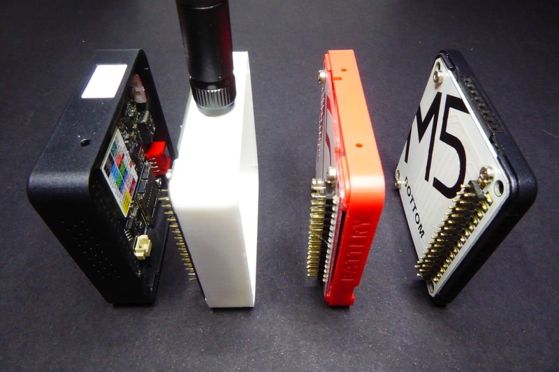
You can spot ten, maybe fifteen different modules for the M5Stack on the Internet. But not all of them are available on their store (which is housed in Aliexpress). Maybe some of them are still in beta. Here you have some links and reference prices. These are affiliate links. If you plan to buy any of these products, clicking on these links will help me keep on working on this blog.
| Product | Link | Price |
|---|---|---|
| Core | Aliexpress | ~31€ |
| Core (with MPU9250) | Aliexpress | ~36€ |
| Battery module (850mAh) | Aliexpress | ~15€ |
| GPS module | Aliexpress | ~35€ |
| Proto module | Aliexpress | ~9€ |
| PLC module | Aliexpress | ~20€ |
| Faces keyboard (expensive but really cool) | Aliexpress | ~141€ |
And, they also have a LoRa module. But wait! I'm not promoting this one because they only sell the 433MHz version… What about the 868MHz, or the 915MHz? Well, this is when this post comes to hand :)
The PCB
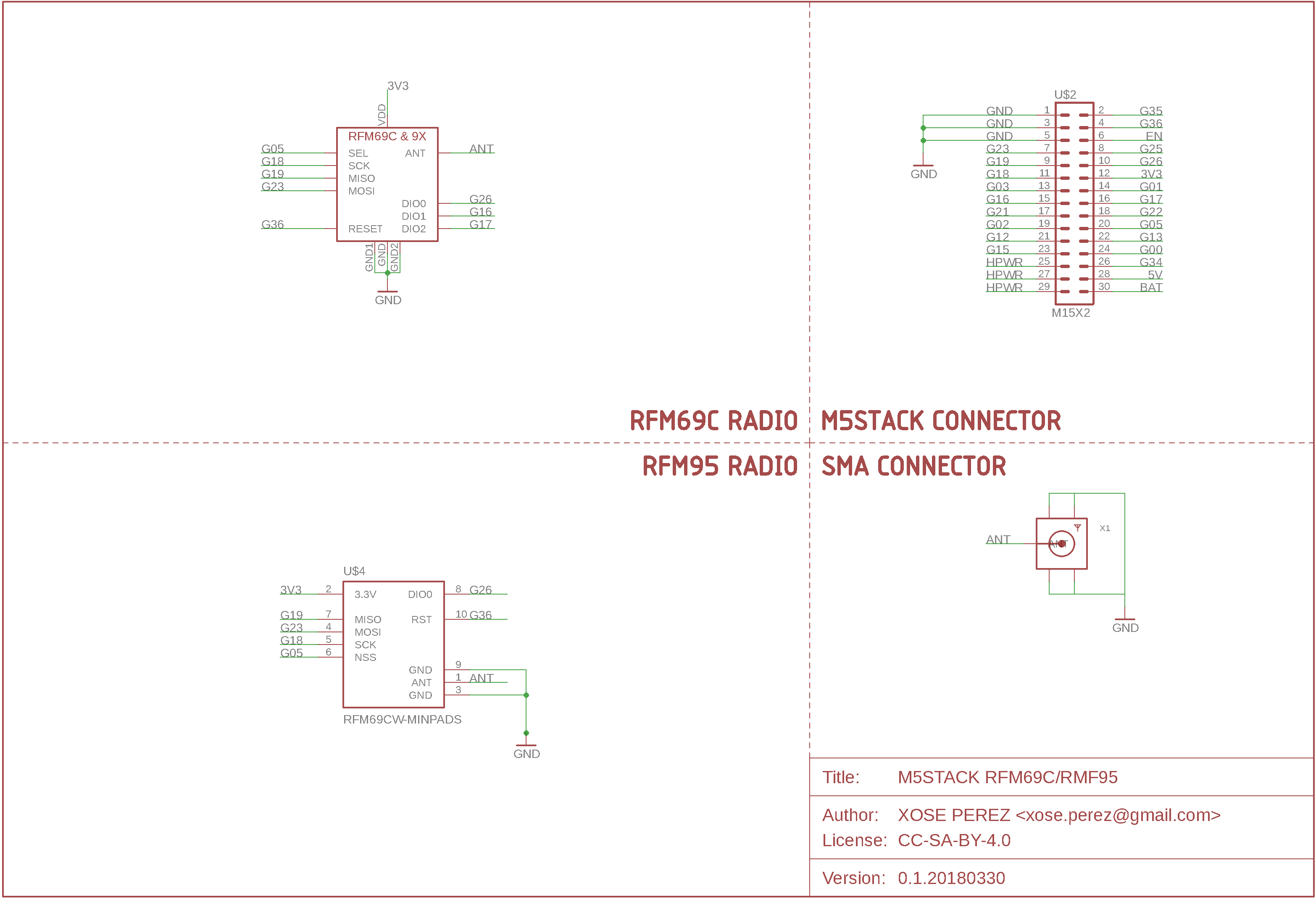
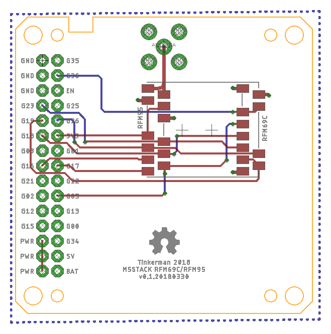
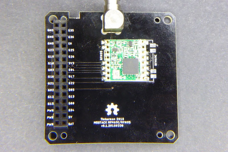
The PCB is very simple. It just routes the required traces from the radio footprint to the header. I added an additional radio footprint using very little additional space. The RFM69C is a FSK 868MHz radio I use at home in some sensors. You cannot have both radios mounted at the same time, of course, but that's a corner use case.
The M5Stack RFM95 PCB is released under the CC-BY-SA-4.0 license as free open hardware and can be checked out at my M5Stack RFM95 repository on GitHub.
I chose to use the same GPIOs as the M5Stack 433MHz LoRa module plus a couple for for DIO1 and DIO2:
| Function | GPIO |
|---|---|
| MOSI | GPIO23 |
| MISO | GPIO19 |
| SCK | GPIO18 |
| SEL | GPIO5 |
| RESET | GPIO36 |
| DIO0 | GPIO26 |
| DIO1 | GPIO16 |
| DIO2 | GPIO17 |
There is also the footprint for a 90 degrees SMA connector in the edge of the board.
A matter of headers
The M5Stack modules use 2x15, 100mil pitch, SMD headers, and even thou I had a few of each (male & female) I realized they would not work, at least not the female ones. The antenna connector adds 9mm of height so I needed higher female headers too.
In the end, I decided not to use the SMD header at all and, instead, use normal ones. But not any normal header will do. The usual 2-row female header have not long enough pins (just enough to let you solder them) and the stackable ones have far too long pins (more than 10mm). I happened to have at home a 2x20 row of the right size: a normal female header on one side and just 5mm of pin length on the male side. These are not usual and I'm struggling to find more. As soon as I do I will post here the link.
The header just fits fine, it has the right height on both sides. The only problem I found is that if you stack another module on top of them (on the female side), the contact is loose so I had to use a pair of nylon screws to keep both layers pressed together.
Improvements
So much free space makes me a little nervous. At the same time it's not a matter of packing stuff there just because you have room. What I will certainly add is a battery connector because it will remove the need to add the battery module. This will allow me to create simple echo nodes with just the Core and the RFM95 layer with a bottom enclosure.
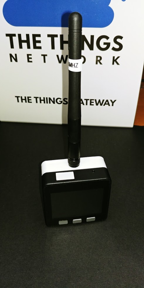
Another issue to take into consideration is the header problem above. If I do not find proper through hole headers I will have to look for other options. Like using high SMD headers…
The enclosure
I designed two different enclosures using OpenSCAD, one for a bottom module and another one for a middle module. They are very similar, of course, 50x50mm, corner tabs to “plug” into the other layers, 4 supports to screw the PCB in and a hole for the SMA connector. The bottom layer is 10mm deep to allow room for the SMA connector and added 4 M3 holes on the bottom to be able to use a nylon screw to hold the layers together.
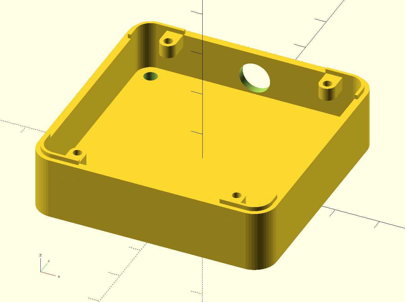
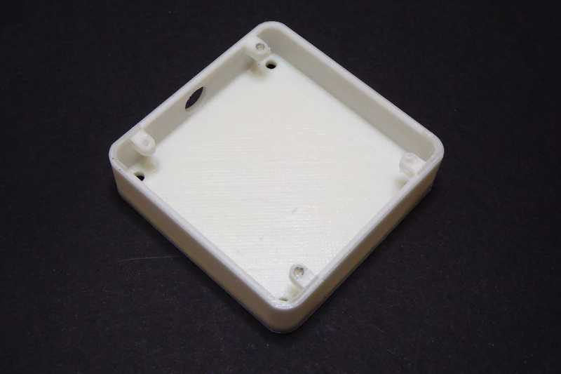
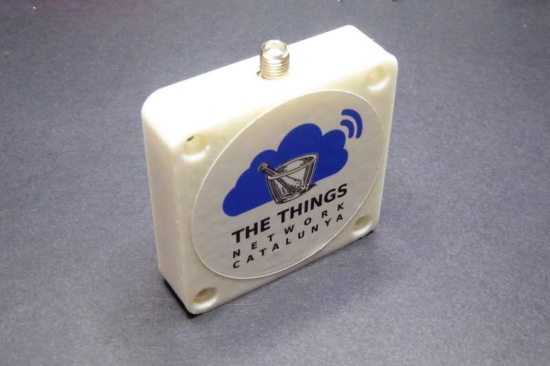
The middle layer walls are slightly higher (12.5mm) due to the required fit between headers. I had to discover this by experimentation. Also, as I said before, I had to use a couple of nylon screws to press the RFM95 module and the battery modules (the red one in the pictures) together. But aside from this “requirement” the fit between layers is perfect, I don't need any other mechanical support so the 4 layers (core, rfm95, battery and bottom) stay together.
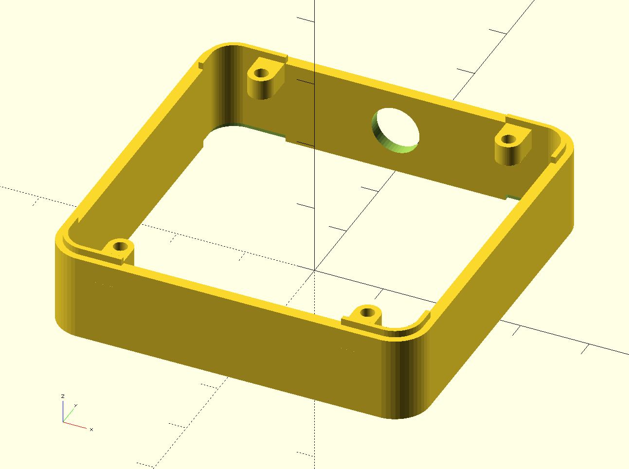
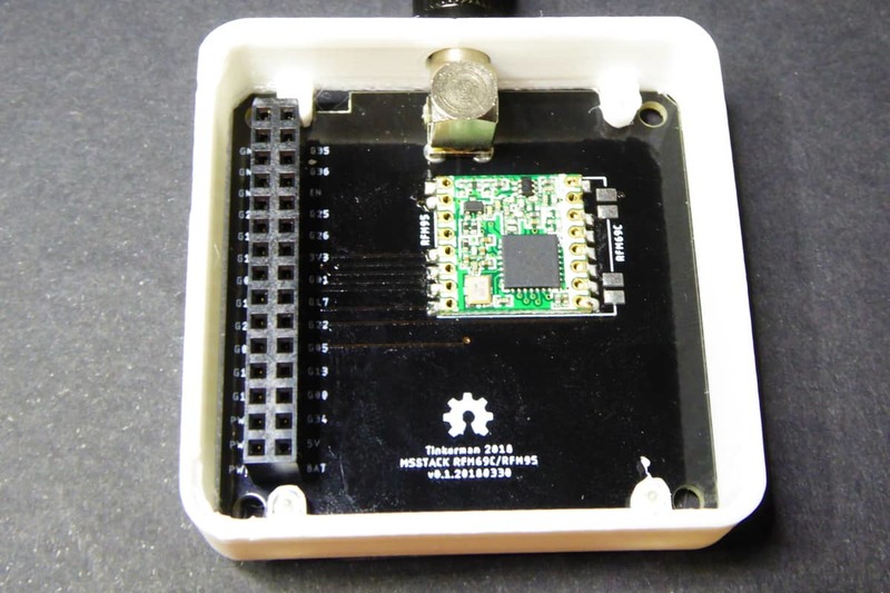
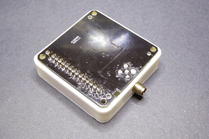
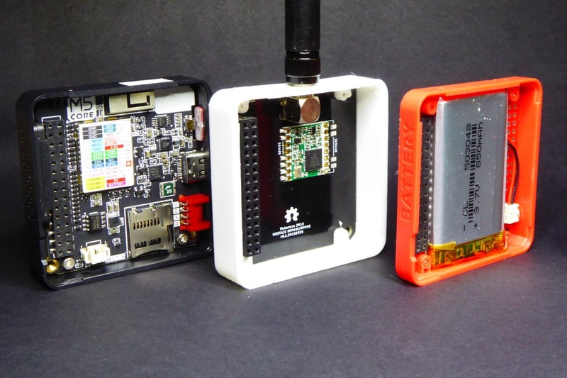
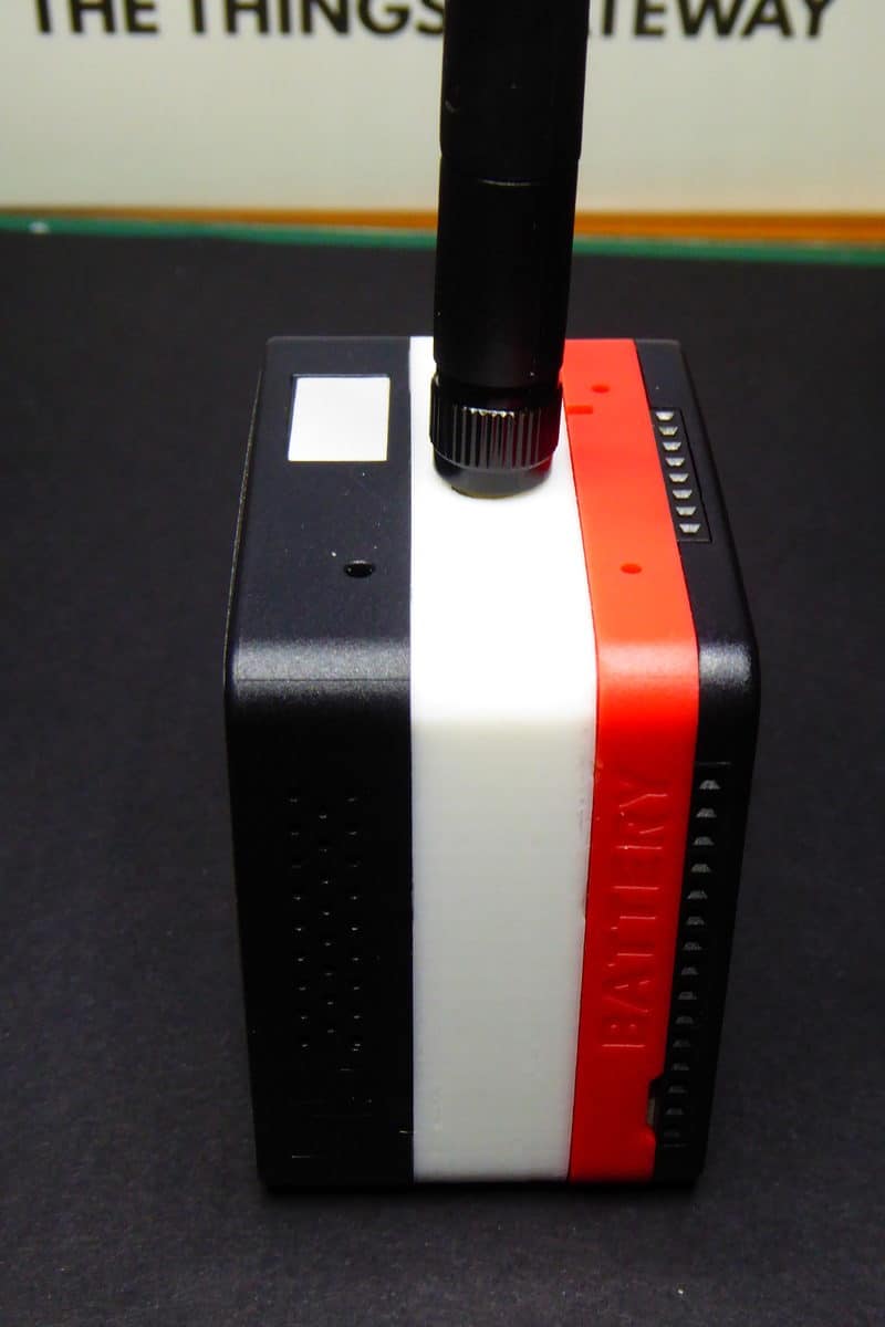
The M5Stack RFM95 3D printable enclosures are released under the CC-BY-SA-4.0 license as free open hardware and can be checked out at my M5Stack RFM95 repository on GitHub.
The code
People at M5Stack have put together a library to use the M5Stack Core from the Arduino ecosystem. This library is available under MIT license on the M5Stach Library repository on GitHub. It exposes an API to manage the LCD screen, the speaker and the action buttons on the Core.
Aside from these specific methods for the Core hardware the repository also contains a number of examples that are a source of additional features and a M5LoRa class. To be honest I have not tried it since I had already planned to use the Arduino-LMIC implementation.
The M5Stack RFM95 example code is released under the General Public License 3.0 (LGPL-3.0) as free open software and can be checked out at my M5Stack RFM95 repository on GitHub.
Arduino-LMIC LoRaWAN stack
The example code uses the Arduino-LMIC library by MCCI Catena, a fork of the original Arduino-LMIC library by Matthijs Kooijman. They are both open source code under the Eclipse Public License v1.0 and available on GitHub.
The MCCI Catena version is more actively developed but the single thing that made me chose it over the original one is that** it does not die with an assert if the radio module is not found**. It might sound like a minor detail, but dying with an assert means the board will stuck in a full powered state with no other option. Now, I can check the result of the _os_init_ex_ method from my application code to see if the module has been correctly configured and notify the user before going into deep sleep mode otherwise.
There are other forks available but I have only tested another one (the NYC TTN group fork). They are mostly the same with some changes to adapt the code to their region networks. The caveat of the MCCI implementation is that they have removed the option to select the region via a build setting, because there is no way to do it from the Arduino IDE. And since they have hardcoded US915 as the default region you need to change it if you are in the UE. They only way to do it is to modify a file in the library itself… not nice :(
The library requires a minimum configuration. On one side you might want to edit the lmic_project_config.h file in the project_config folder o match your region settings. Then you will have to tell the library the GPIOs it has to use (SPI, RESET and interrupts). The code is pretty simple and you will probably see it in every example of this library:
#define SCK_GPIO        18
#define MISO_GPIO       19
#define MOSI_GPIO       23
#define NSS_GPIO        05
#define RESET_GPIO      36
#define DIO0_GPIO       26
#define DIO1_GPIO       16
#define DIO2_GPIO       17

const lmic_pinmap lmic_pins = {
    .nss = NSS_GPIO,
    .rxtx = LMIC_UNUSED_PIN,
    .rst = RESET_GPIO,
    .dio = {DIO0_GPIO, DIO1_GPIO, DIO2_GPIO},
};
With the example code for this M5Stack-based node, you will have to copy-paste and rename the credentials.h.sample file to credentials.h and edit it to match your device settings.
Scrolling the screen
The LCD controller is an ILI9341 [datasheet, PDF] connected with the ESP32 via SPI. It has some powerful features which are not available by default on the M5 LCD library. One of these features is a kind of block copy-paste you can use to scroll your screen.
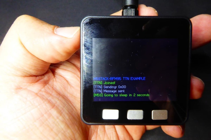
Scrolling the screen might not be necessary, not even with this project where the screen will show a few lines every time before going back to sleep, but if you are not sleeping the device and you want a message log it is very handy.
The code for the scrolling is taken from the TFT_Terminal example in the M5Stack library with just some (heavy) clean-up. A custom screen_print method handles the text printing (with optional color) and scrolling.
Images
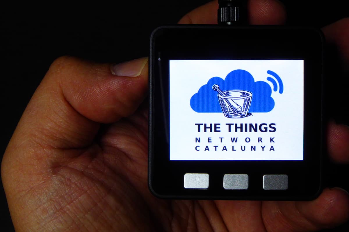
Another fancy feature is the ability to show 320x240 16-bits images. There is post on the M5Stack forum that explains how to do it but I found the info not accurate and, anyway, the suggested tool works only under Windows. But there was enough info there to find out how to do it.
- Get the image you want. Rescale it to 320x240 and flip it vertically.
- Save your image as a 16-bits BMP (5R6G5B). Using GIMP you can find this option under the “Advanced options” text in the “Export Image as BMP” dialog just after you name the file.
- Use the bin2code.py script under the tools folder in my repo to convert it to a C array.
- Add the reference in you code to the array as external.
- Use the M5.Lcd.drawBitmap method to draw the image to the screen.
The bin2code.py file is a modified version of the one that comes with the M5Stack library. It fixes a bug in the data reading and also bypasses the BMP header (maybe that other tool does not generate it?).
Deep sleep on battery issue
There is one final issue with the M5Stack Core. It does not support deep sleep while on battery. This is a problem with the IP5306 power management chip. Apparently it enters into stand-by mode after 32 seconds of “no activity” (less than 45mA load). This means that if you turn off the screen and go into deep sleep for more than that, you won't be able to wake up… The issue was reported in the forums but the proposed fix requires a hardware change. It will be fixed for future versions of the M5Stack Core but we will have to live with it with the current ones.
The solution I used is the same we all use for our AVR projects. AVR chips (the ones in the most common Arduino boards) can only sleep for up to 8 seconds in a row. If you want to sleep longer you have to do several “naps” until the total time is the one you initially wanted.
Here I used a cool feature of the dual-core ESP32: the RTC memory. When in deep sleep the main core of the ESP32 shuts off and only the low power secondary core is partially awake, enough to power the RTC that's responsible to trigger the waking up process. But the RTC also has an internal memory you can use to persist data across sleeps. And you only have to specify RTC_DATA_ATTR when defining variables you want to be stored in the RTC memory:
// Number of sleeping intervals left, stored in RTC memory, survives deep sleep
RTC_DATA_ATTR uint8_t sleep_intervals = 0;
Now when going to sleep for an arbitrary amount of time we must calculate how many sleep periods we will have to sleep. First I define a sleep period length of 30 seconds (just below the 32s when the IP5306 goes into stand-by-mode).
#define SLEEP_INTERVAL          30000       // Sleep for these many millis
#define SLEEP_DELAY             500         // Time between sleep blocks to keep IP5306 on
And now I do the maths just before going to sleep:
// Set the left most button to wake the board
sleep_interrupt(BUTTON_A_PIN, LOW);

// We sleep for the interval between messages minus the current millis
// this way we distribute the messages evenly every TX_INTERVAL millis
uint32_t sleep_for = TX_INTERVAL - millis();

// How many sleep blocks do we have to sleep?
sleep_intervals = sleep_for / SLEEP_INTERVAL;

// Trigger the deep sleep mode
// The first block might be shorter than SLEEP_INTERVAL
sleep_millis(sleep_for % SLEEP_INTERVAL);
Now the board will awake every (at most) 30 seconds. When waking up from a deep sleep we will have to check if we have to go back to sleep or not. We will also need to check if we have awaken the board manually clicking the action button. Unfortunately there is no way to know the wake reason, so we rely on checking the button state in the hope that the user is still pressing it. So if you want to really awake the board, press the button and hold it down until you see the message in the screen. This will take only a few hundreds of millis, so unless you are a fast-clicker it will work.
// Awake from deep sleep (reason 5)?
if (5 == rtc_get_reset_reason(0)) {

    // Is the button pressed (HIGH means "no")?
    if (digitalRead(BUTTON_A_PIN) == HIGH) {

        // If we are not done yet...
        if (sleep_intervals > 0) {

            // Update the number of intervals left
            --sleep_intervals;

            // Delay a bit so the IP5306 notices it
            delay(SLEEP_DELAY);

            // And go back to sleep
            sleep_interrupt(BUTTON_A_PIN, LOW);
            sleep_millis(SLEEP_INTERVAL - millis());

        }
    }
}
Wrap up
The M5Stack makes a great looking prototyping platform and this won't be the only project I will be doing with it. Now I have a TTN node I can use to monitor the TTN coverage with TTN Mapper or using (abusing) ACKs. But not only this, I will probably replace my RFM69GW with a M5Stack based one and monitor my home WSN messages on its screen.
It's good to see that there are already some nice ESP32 devices available (aside from the usual prototyping ones). So we can little by little start migrating our projects to this beast… ESPurna you said?
"M5Stack node for The Things Network" was first posted on 10 June 2018 by Xose Pérez on tinkerman.cat under Code, Projects and tagged 3d printing, ack, ailight, arduino, deep sleep, esp32, lmic, lora, lorawan, m5stack, mpu9250, rfm69, rfm69c, rfm69gw, rfm95, the things network, ttn, ttnmapper.