Solr: digital wrist watch
15 months ago. This is when I started working on this project. The Solr digital wrist watch is a clock that won’t work without a battery but it will neither work without sun. Even more: the vintage display is really cool but it’s hard to read outdoors. A complete nonsense. It is almost a joke and some might easily file it under the “useless projects” label.
But it's still quite useful. Whether you don't care about accuracy, or if you need an excuse to always be late. Or maybe you want your daughter to raise her eyebrowns and tenderly call you a “freak”. Either case I suggest you to proudly wear a Solr.
The idea
The original idea was quite naive: a** digital sun dial**. The azimut of the sun can be translated into the current solar time. When the sun is at the south the time is solar noon. This is not exact since the Earth has a small preceding east-west yearly movement that can account for up to a 16 minutes drift. This difference is known as the equation of time.
But 16 minutes mean 4 degrees and I was first concerned about the accuracy of the magnetometer and the human wearing it. So I decided to start over and test the accuracy along the path.
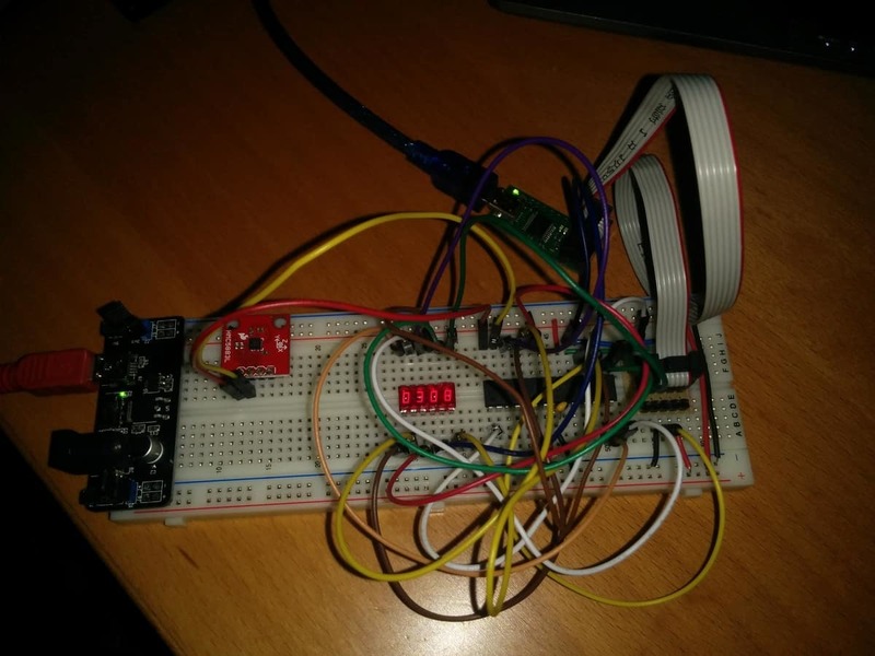
The first prototype was the usual wire mess on a breadboard, using a DIP ATMega328P.
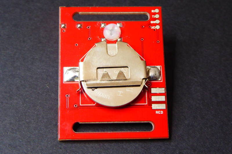
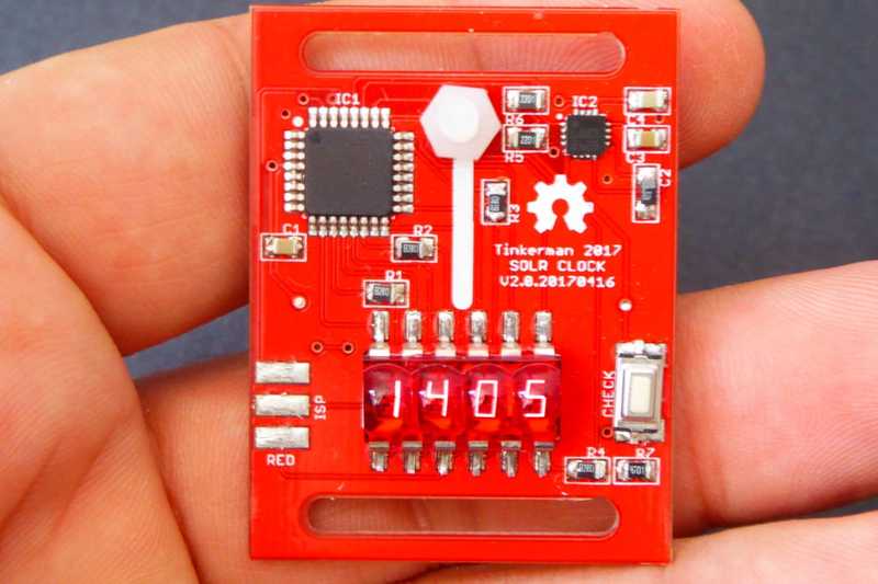
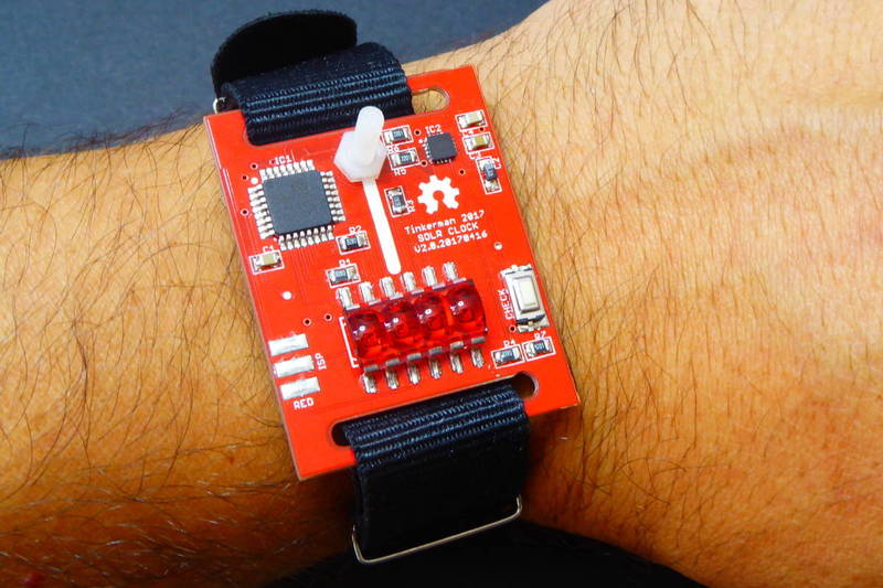
And 15 months passed from that prototype to the current board, named version 2.0. The board is inspired in the RetroSmartWatch (I can't find the reference now) using two slits to pass by the watch belt that hides the coin cell behing the board. The front face of the clock resemble (or at least that's what I tried to) a face with two eyes (the microcontroller and the open hardware logo), a nose (the white line where you have to align the shadow of the nylon screew) and the bottom slit as a mouth. The retro display might as well look like a purple moustache, weird.
Weld hard
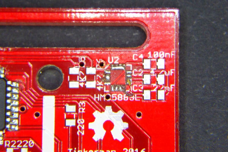
Between the breadboard prototype and version 2.0 there was, of course, a version 1.0 board. It was not that different from 2.0 but I made a fatal mistake: I had too much confidence on my welding skills. An HMC5883L LCC package is just too hard to hand solder.
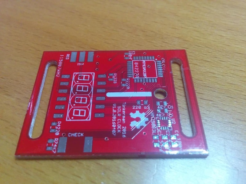
My efforts ended up in 3 boards and two chips in the bin. That almost made me quit the project.
Seeedstudio PCBA
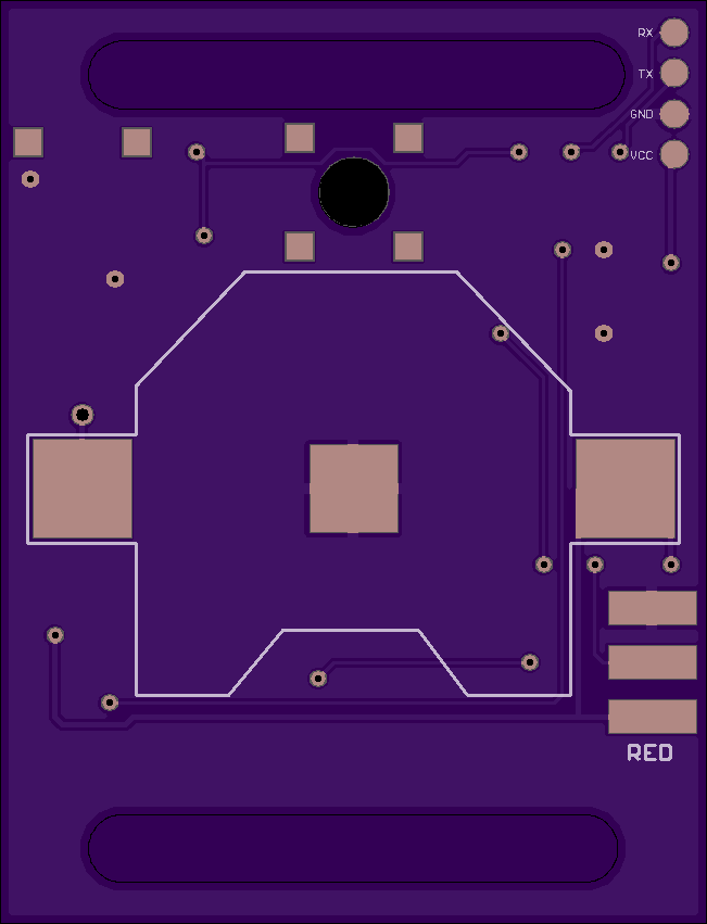
Then, a couple of months ago I started thinking about using Seeedstudio PCBA service. They offer a really good price and have a more than 600 references. But the best part was that the HMC5883L is one of those references. I modified the board using SeeedStudio's OPL parts and exported the BOM but I finally decided to populate only the ATMega328P IC and the HMC5883L sensor.
Ten boards with 2 components each for 93 euros plus shipping. Not bad.
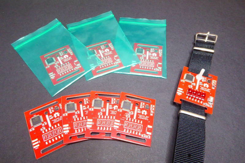
Always triple check
While redoing the connections with the new footprints I did a second fatal mistake. The worst of all: connected a VCC line to ground. The error was in one of the legs of the AVR microcontroller so I simply sliced it off in the hope that all grounds were connected inside the chip.
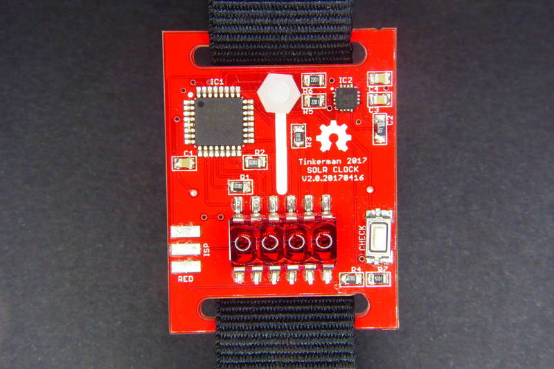
The mistake is fixed with version 2.1, available at the repo.
Fortunatelly my computer USB port simply switched off when it detected the short circuit. So after the small surgery I was finally able to flash the chip and start with the firmware part.
AVR ISP 6 pin edge connector
One of the decisions was to test a different programming header. I wanted it to have a small footprint but at the same time I didn't want (or force anyone) to buy cool and/or expensive programming tools like a pogo pin connector. An ISP header was OK but it still used too much space on the board. And then I saw those AVR ISP 6 pin edge connectors on upverter.com and decided to give them a try.
You will need an AVR programmer with a 6 pin converter to flash your code, but if you have worked with AVR beyond the Arduino world you very likely have one already. Else it's a useful tool to have, you can buy it in Ebay or Aliexpress for less than $3.
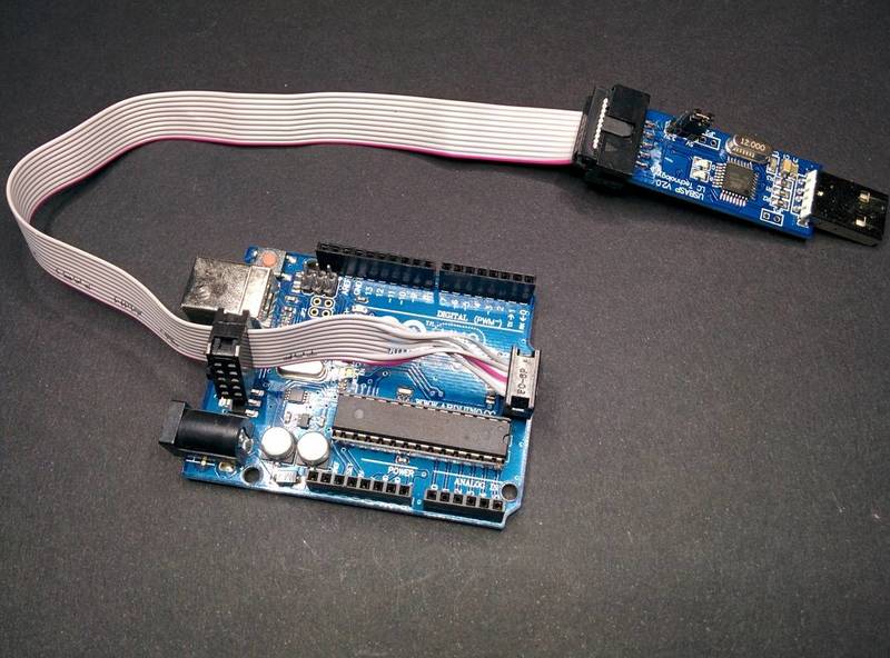
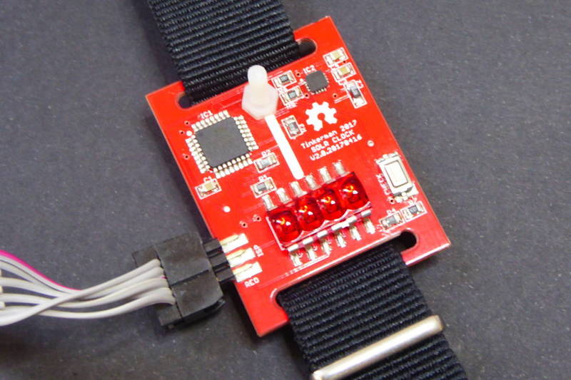
They work although they are not 100% reliable. You might want to add a bit of tin on the connectors on one side of the board and bend a bit the male header so it fits tight on both sides of it. But overall they are doable. I think they are even a better option than using pogo pins since you will have to hold them manually in place.
A nice display
It won't be fair not to say that the project was also an excuse to use that cool seven segments display. Its one of the key components of the project. The HP QDSP-6064 display [datasheet, pdf] is a common cathode 4 digit seven segments display with a retro look I had already used in a previous project. It's so cool.
They are somewhat hard to find. Last time I bought 10 units from Ebay. Right now there seems to be only one seller with them in stock. They are being sold as Retro 4-digit BUBBLE VINTAGE rare red LED Display QDSP6064 [Ebay].
The display is driven directly from the ATMega328P microcontroller since it has enough GPIOs for that. But since I wanted it to be SMD I bent and cut the legs and created a specific footprint on Eagle for them.
Sant Pol, what time is it?
Some of you might know I live in a small town north of Barcelona named Sant Pol. It used to be a fishermen town, small and quiet, far from being one of the crowded touristic beach towns in the zone. There is a legend (they say a false myth) that tells that a long time ago people from Sant Pol restored an old sun dial that had been corrupted by the action of sun and rain. To prevent that from happening again they decided to cover the sundial with a roof top, effectively driving it useless. Since then people from neighbours town used to laught at people from Sant Pol saying “Sant pol quin'hora és?” (Sant Pol, what time is it?) whenever they happen to meet a local.
Well, you know what? That bubble display is really cool but it's also really hard to read outdoors. So after aligning the sun shadow on the white line and pressing the button you better find a dark place to actually read the time. You have 5 seconds to do so.
Calibrating the HMC5883L
Before using the compass we should first calibrate it. Calibration procedure is explained in the HMC5883L [pdf] datasheet page 24. It basically consists on truning the chip slowly on the XY plane twice or three times on a minute and record values for X and Y magneting readings. Then use those values to find out the offset and scale factors for both axix. The procedure should be done in a place far from magnetic disturbances (metals, magnets,…) to avoid external fields.
To do that I've implemented a library that uses the I2Cdevlib-HMC5883L library by Jeff Rowberg. The library has some convenient methods to get the heading vector or the bearing angle, it also has the calibration method and internal methods to store the calibrarion values in the microcontroller EEPROM.
void Compass::calibrate(byte mode) {

   int x, y, z;

   #if HMC5883L_DEBUG == 1
      Serial.println("Calibrating Magnetometer");
   #endif

   if (mode & HMC5883L_CALIBRATE_GAIN) {

      // Positive bias
      HMC5883L::setSampleAveraging(HMC5883L_AVERAGING_8);
      HMC5883L::setDataRate(HMC5883L_RATE_15);
      HMC5883L::setMeasurementBias(HMC5883L_BIAS_POSITIVE);
      HMC5883L::getHeading(&x, &y, &z);
      while ((x<200) | (y<200) | (z<200)) HMC5883L::getHeading(&x, &y, &z); x *= _gain_factor; y *= _gain_factor; z *= _gain_factor; _x_gain_error = (float) HMC5883L_COMPASS_XY_EXCITATION / x; _y_gain_error = (float) HMC5883L_COMPASS_XY_EXCITATION / y; _z_gain_error = (float) HMC5883L_COMPASS_Z_EXCITATION / z; // Negative bias HMC5883L::setMeasurementBias(HMC5883L_BIAS_NEGATIVE); HMC5883L::getHeading(&x, &y, &z); while ((x>-200) | (y>-200) | (z>-200)) HMC5883L::getHeading(&x, &y, &z);
      x *= _gain_factor;
      y *= _gain_factor;
      z *= _gain_factor;
      _x_gain_error = ((float) HMC5883L_COMPASS_XY_EXCITATION / abs(x) + _x_gain_error) / 2;
      _y_gain_error = ((float) HMC5883L_COMPASS_XY_EXCITATION / abs(y) + _y_gain_error) / 2;
      _z_gain_error = ((float) HMC5883L_COMPASS_Z_EXCITATION / abs(z) + _z_gain_error) / 2;

      // Recover initial configuration
      HMC5883L::setMeasurementBias(HMC5883L_BIAS_NORMAL);

      #if HMC5883L_DEBUG == 1
         Serial.print("Gain (x, y, z): ");
         Serial.print(_x_gain_error);
         Serial.print(", ");
         Serial.print(_y_gain_error);
         Serial.print(", ");
         Serial.println(_z_gain_error);
      #endif

   }

   if (mode & HMC5883L_CALIBRATE_OFFSET) {

      #if HMC5883L_DEBUG == 1
         Serial.println("Rotate magnetometer 2 or 3 times within 1 minute....");
      #endif

      for (byte i=0; i<10; i++) HMC5883L::getHeading(&x, &y, &z);
      float x_max = -4000;
      float y_max = -4000;
      float z_max = -4000;
      float x_min = 4000;
      float y_min = 4000;
      float z_min = 4000;
      _x_offset = _y_offset = _z_offset = 0;

      unsigned long timeout = millis() + 60000;
      while (millis() < timeout) {
         HMC5883L::getHeading(&x, &y, &z);
         x_max = max(x_max, x);
         y_max = max(y_max, y);
         z_max = max(z_max, z);
         x_min = min(x_min, x);
         y_min = min(y_min, y);
         z_min = min(z_min, z);
      }

      _x_offset = (( x_max - x_min) / 2) - x_max;
      _y_offset = (( y_max - y_min) / 2) - y_max;
      _z_offset = (( z_max - z_min) / 2) - z_max;

      #if HMC5883L_DEBUG == 1
         Serial.print("Offset in mG (x, y, z): ");
         Serial.print(_x_offset);
         Serial.print(", ");
         Serial.print(_y_offset);
         Serial.print(", ");
         Serial.println(_z_offset);
      #endif

   }

   _eeprom_put();

}
Don't try it at home
Or do it under the risk of ruining your reputation.
The Solr code is released under GPLv3 license, the schematics and layout is released under the Creative Commons Attribution-ShareAlike 3.0 Unported License (CC-BY-SA 3.0) and follows the terms of the OSHW (Open-source hardware) Statement of Principles 1.0. It can be checked out at my solr repository on Bitbucket.
"Solr: digital wrist watch" was first posted on 17 June 2017 by Xose Pérez on tinkerman.cat under Projects and tagged atmega328, avr programmr, bubble display, edge connector, equation of time, hmc5883l, opl, pcba, qdsp-6064, seeedstudio, solr, usbisp.