Smartmeter pulse counter (1)
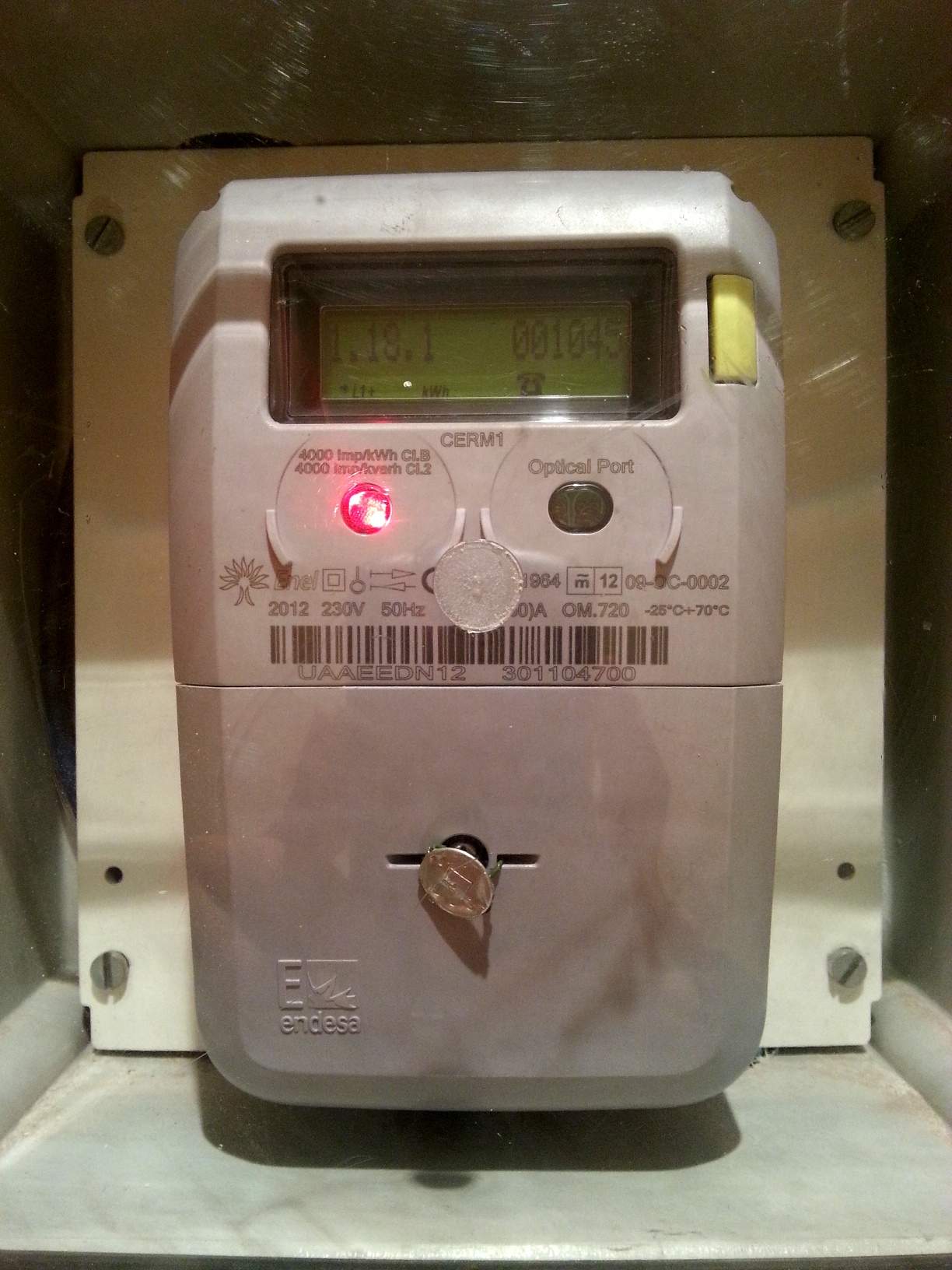
Endesa has recently updated my home energy meter to meet new UE and Spanish regulations. The new meter it's a smartmeter by Meters and More and it basically provides the means to perform remote meter readings and supply changes. The goal of the new regulation is to provide better and more accurate information to final customers regarding their energy consumption habits to promote energy efficiency and saving.

The reason I'm writing about this is that the meters has two communication ports on the front side, an I/O optical port with unknown protocol and a simple LED labeled “4000 Imp/KWh”. This means that every 4 pulses you have used 1Wh of energy or the equivalent: 1 pulse/sec its 900W of instantaneous power consumption (2 pulses/sec 1800W, 3 pulses/sec 2700W or 1 pulse every 2 secs 450W and so on).
So I'm planning to set up a simple pulse counter and send the information to my IoT gateway and store it somewhere. The idea is to use a voltage divider with a resistor and a photocell with the output attached to one of the hardware interrupt pins of an Arduino Mini Pro. The resistor should be at least four times bigger than the resistance of the photocell when illuminated by the pulse light so the Arduino would interpret it as a HIGH. Then count the pulses in the interrupt method and either send a message to the server every say 40 pulses (10 Wh) or every minute using a RTC with an alarm triggering the other interrupt pin in the Arduino.
The first critical issue was to be able to accurately count all the pulses. I was sceptical about using software debouncing since the processor will be busy with turning on the radio and sending the data for maybe one second every minute and it won't be able to debounce incoming pulses in the meantime so I needed clean signals in the interrupt pin.
I did some quick tests with a CdS photocell in a voltage divider configuration with a 47kOhm resistor and the response of the sensor seemed to be good enough to capture the pulse. The photocell resistance easily dropped below 5kOhms and the pulse looked like some 50ms width. But I needed more precise readings.
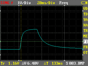
And here it came the DSO Nano v2 to the rescue. I attached the probes to the voltage divider output and to ground and after some testing trying to find the right parameters in the scope I managed to get a pretty decent image of the output.

The image shows a pulse with 2.96 Vpp (I was using a 3V3 source) and some 50ms width. The pulse has soft rising and falling edges that resemble those from a RC circuit (albeit one very curious RC circuit with a time constant of around 10ms when rising and 20ms when falling).
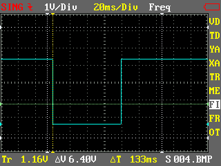
Good news is that the output seems ripple-free so there is no need for further softening and I can just plug it to a Schmitt trigger to get sharp edges. I used a 74HC14 I had from another (unfinished) project around although the packaging is a little overkill (I'm only using 1 of the 6 gates it has).

The final pulse has sharp edges and is 80ms width. This gives me time to capture up to 12 pulses per second. That would be a instantaneous power consumption of 10.8kW which is almost double I have at home.
So far so good.
"Smartmeter pulse counter (1)" was first posted on 29 October 2012 by Xose Pérez on tinkerman.cat under Learning, Projects and tagged debouncing, dso nano, pulse, schmitt trigger, smart meter.