Moteino Door Monitor
Some days ago I posted about the RFM69 to MQTT gateway based on the ESP8266 I am working on. Over these days I've been fine tuning the gateway at the same time I was migrating one of my home sensors to Moteino: the Door Monitor. The previous version was based on an XBee radio and has been on duty for almost 3 years and a half. Real life battery time has been around 3 months for a CR2032 coin cell, which is not bad at all, but still…
Aside from using a Moteino and a RFM69 868MHz radio instead of the XBee, I have reduced the components list by moving hardware logic to software logic. This means using sleeping capabilities of both the ATMega328 and the RFM69 and coding in a clever way to reduce awake time.
Hardware
As I said, hardware is much simpler in this second version of the door monitor, you can check here both “generations” side by side:
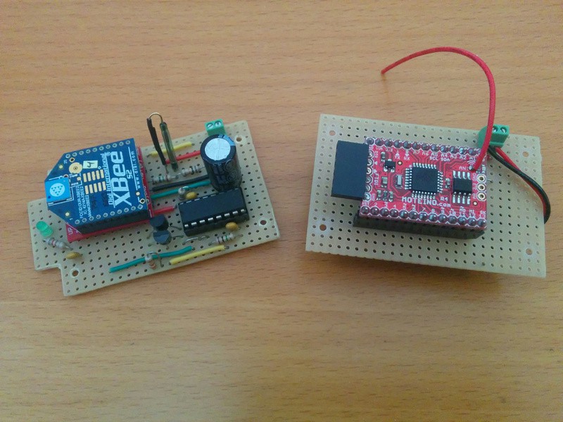
This second generation is basically a Moteino with a RFM69W on board, a voltage divider to monitor battery, a reed switch with a pull-up and a screw terminal to connect a battery. That's it. The reasons to move to a Moteino were mainly 3:
- Better customization. XBees are programmable, but really, who does that? So here you have a good-old Arduino with enough processing power to use almost any sensor out there.
- Longer battery life. You have more options from code, like putting the radio, the flash chip and the microcontroller itself to sleep. Besides I wanted to include a beefier battery solution, like 3-AAA batteries with >1000mAh.
- Easier to use. I had my share of the X-CTU software over Wine.

There are a few things to note hardware-wise. First the** battery monitor** has been designed after John k2ox post in the LowPowerLab forum. The voltage divider consists on a 470k and a 1M resistors. The downstream resistor is not tied to GND but to digital pin 12. When this pin is in high impedance mode the circuitry is disabled and no power is wasted. To measure voltage you first have to set it to OUTPUT and then LOW, do an analogRead in A1 and put D12 back to INPUT.
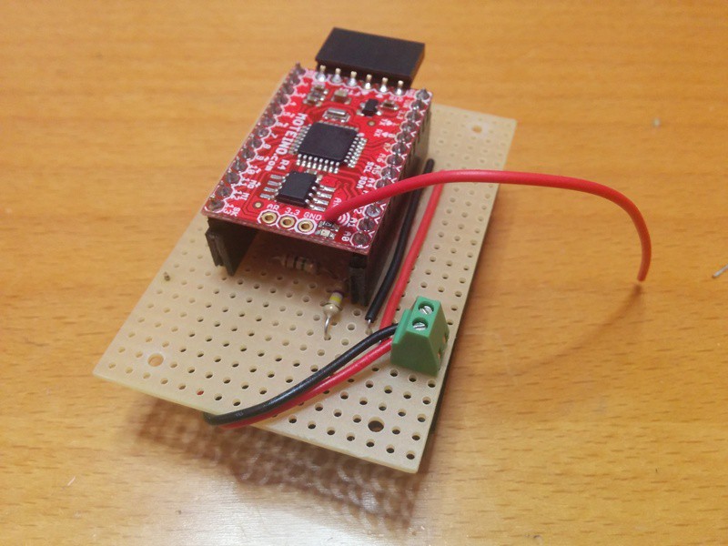
Second the pullup resistor in the reed switch was a late addition to check weather there was a drop in power consumption compared to the internal pullup. But there wasn't. I'm a bit surprised by this fact but I couldn't get a different result. To see how I did the measurement look for the Power section below.
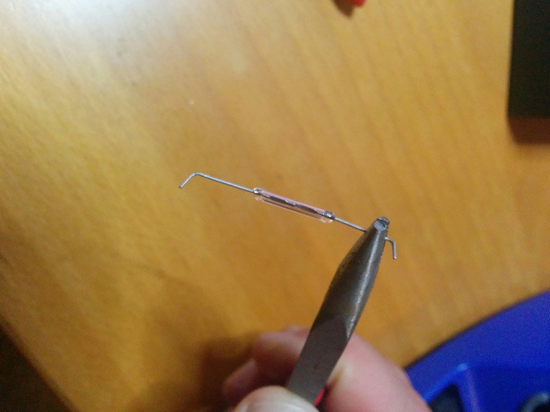
Also, this might not look important but it could save you some (little) money and a lot of headache. Those** reed switches are reaaaally fragile**. The critical moment is when you have to bend its legs. After breaking some of them, I always use a small plier (a needle nose one) to hold the leg just before the bending point, so the capsule is protected in one side of the plier and I gently bend the other end. Check the picture:
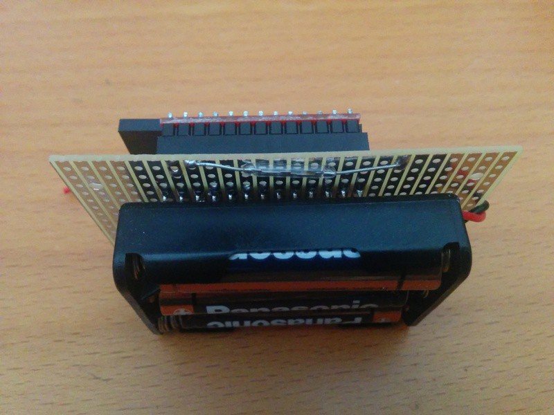
And finally, test what is the best position for the reed switch and the magnet. For round neodinium magnets the switch should be perpendicular to the plane of the magnet (check the header image in this post) and this one:
Firmware
The code is quite simple, it relies on Felix Rusu and Thomas Studwell RFM69_ATC and RocketScream Low-Power libraries. The reed switch is tied to an interrupt pin that awakes the Moteino whenever it changes it's state. Then the code debounces the signal and checks if the value has changed. I started with a 25ms debounce time and later I checked with my DSO Nano that 5ms is more than enough. Signal and messaging looks a lot more reliable than with the XBee, where I had bounces and ghost signals (a door open and closed trigger two messages and seconds after, two more messages).
This is the loop code responsible for the sleeping and awaking of the microcontroller:
void loop() {

    // We got here for three possible reasons:
    // - it's the first time (so we report status and battery)
    // - after 4*15 seconds (we report status and maybe battery)
    // - after an event (same)
    send();

    // Sleep loop
    // 15 times 4 seconds equals 1 minute,
    // but in real life messages are received every 77 seconds
    // with this set up, so I'm using 13 here instead...
    for (byte i = 0; i < 13; i++) {

        // Sleep for 8 seconds (the maximum the WDT accepts)
        LowPower.powerDown(SLEEP_4S, ADC_OFF, BOD_OFF);

        // At this point either 4 seconds have passed or
        // an interrupt has been triggered. If the later
        // delay execution for a few milliseconds to avoid
        // bouncing signals and break
        if (flag) {
            flag = false;
            delay(DEBOUNCE_INTERVAL);
            break;
        }

        // If the former, check status and quit if it has changed
        if (status != digitalRead(REED_PIN)) break;

    }

}
The status variable holds the last status sent and acknowledged by the gateway. So if we are missing an ACK the code will try to send the same message again in four seconds. You can check the full code at my Door Monitor repository on Bitbucket.
I'm using a wrapper library (RFM69Manager) to manage the radio setup and message format. Messages are in the format:
key:value:packetID
Like in “BAT:4302:34”. The packet ID is optional but my RFM69GW uses it to check for duplicates or missing packages. It can be disabled changing the SEND_PACKET_ID value in RFM69Manager.h to 0.
Sleeping the Moteino
Power is key in this project since the sensor will be battery operated. In the first generation, with the XBee, it could work for about 3 months on a single ~300mAh CR2032 coin cell. For this second generations I wanted both more autonomy and reliability. Reliability often is a trade of with power consumption: more checks, more messages, more time awaken.
I own a poor guy's DSO Nano oscilloscope that is good enough for a poor engineer like me, and I recently bought a uCurrent Gold from EEVblog and this is the perfect project to test it! First some static values using the multimeter.
| Controller | Radio | mA |
|---|---|---|
| ON | ON | 8.5 |
| ON | OFF | 7.5 |
| OFF | ON | 1.34 |
| OFF | OFF | 0.015 |
The uCurrent was set to 1mV/1mA for all the values except the last one, that required the next level of precision: 1mA/1uA. This last value is roughly twice the minimum in the Moteino specifications… don't know why.
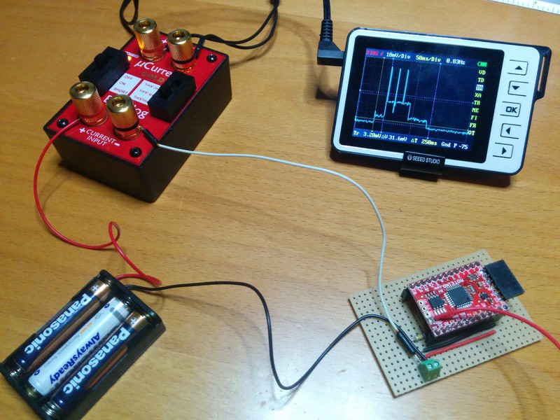
The there is the transmission. Here I fastened my DSO Nano probe to the voltage output terminals in the uCurrent. And capture some nice graphics:
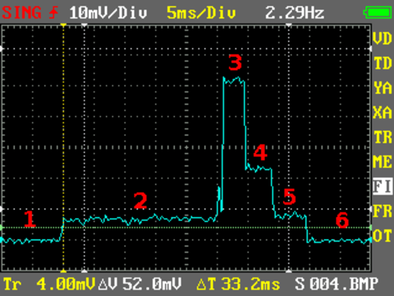
The different stages in the graph are described in the following table:
| Stage | Description | mA | ms |
|---|---|---|---|
| 1 | Everybody is sleeping and suddenly… an interrupt | ||
| 2 | The microcontroller awakes and debounces the signal | 7.2 | ~25 |
| 3 | Radio sending | 20-56 | ~4 |
| 4 | Radio waiting for ACK | 23 | 4.4 |
| 5 | Radio off and blinking LED | 7.2 | 5.4 |
| 6 | Everybody back to sleep |
You can easily spot the DEBOUNCE_INTERVAL (#2) and the NOTIFICATION_INTERVAL (#5) in the graphic. I later changed the DEBOUNCE_INTERVAL to 5ms so #2 is 5 times shorter. Also radio pulses (#3) vary depending on the transmitting power. Since Auto Transmission Control is enabled the radio will modify the transmitting power to match the given target (RSSI -70) so first bursts will use more power and it will eventually go down to a stable lower value. I have seen burst at -60 RSSI that used less power than the radio waiting for the ACK (is that even possible?). Know more about Auto Transmission Control in this post by Felix Rusu.
Normally the sender will receive an ACK in a few milliseconds (#4) and will go back to sleep. But if the gateway is too busy or the ACK gets lost the sender will retry after 40ms up to 2 more times. So the total time with the radio awaken can be 120ms + 3*4ms for each radio burst. But this rarely happens.
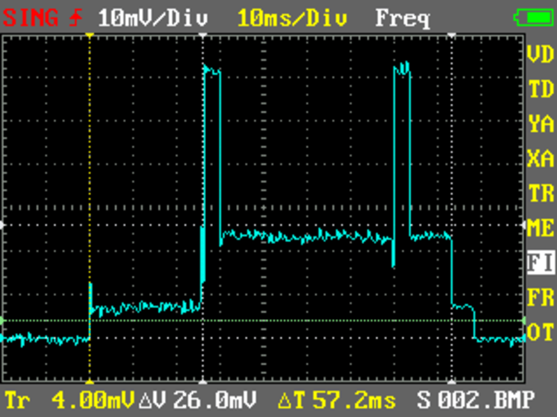
Note that the debounce time only applies if there has been an interrupt caused by the reed switch. At home that could happen like 20 times a day. But the non-interrupt message, the heartbeat the sensor sends every minute does not have this leading time (check code above). So the normal operation would be: a heartbeat without debounce time, one single spike with a quick ACK form the gateway (averaging 4-5ms) and a nice LED blinking for 5ms at the end (off course I could get rid of this but it's good to have some kind of visual notification).
And finally we should take into account that every 10 messages the node sends the battery reading. Let's do the math:
| Stage | mA | ms/event | events/minute | mA*ms/minute |
|---|---|---|---|---|
| Sending burst | 56 | 4 | 1.1 | 246 |
| Waiting ACK | 23 | 5 | 1.1 | 126 |
| Blinking LED | 7.2 | 5 | 1 | 36 |
| Rest of the minute | 0.015 | 60000-4.4-5.5-5 | ~900 | |
| Total over a minute | ~1309 |
This averages to 22uA (1309mA*ms/minute / 60000 ms/minute). A 1000mAh battery would last almost 46000 hours or more than 5 years!!
These calculations are assuming high power messages, 1 battery message every 10 status messages (hence the 1.1 events per minute), no interrupts (like if the whole family was on holidays) and perfect communication with the gateway (i.e. quick ACKs). Door events would add little to this and right now the gateway is responding 99% of the times within the first milliseconds… that off course could change as it has more messages to process. On the other side ATC will even improve these numbers. Time will tell. Right now numbers on paper (or blog) look gorgeous. Let's see what numbers do real life.
Code and schematics for this project are released as free open software and hardware and can be checked out at my Door Monitor repository on Bitbucket.
"Moteino Door Monitor" was first posted on 26 August 2016 by Xose Pérez on tinkerman.cat under Code, Projects and tagged ack, atc, auto transmission control, battery monitor, cr2032, debouncing, dso nano, esp8266, fritzing, low power, lowpowerlab, magnet, moteino, mqtt, power measurement, reed switch, rfm69, rfm69gw, ucurrent gold, xbee.