Analyze your antennas using an AAI N1201SA
Following up with the series of affordable RF tools I started with the RF Power Monitor 8000, maybe the N1201SA by Accuracy Agilty (sic?) Instrument (AAI) is one of the most exciting devices around. The device is sold as “RF Vector Impedanze Analyzer” and, although it's not a full VNA (Vector Network Analyzer), it gives you enough information to profile your antennas and, according to some reviews, it's so accurate it can compete with professional equipment. It's mind blowing that you could get such a device for just around 138€ in Aliexpress or $152 from Amazon if you are buying from the US.
Updated on 2019-06-03 with some appreciations about common elbow antennas.
Features
I'm not going to review the device in depth. I couldn't do it better than Andreas Spiess did in this video about optimizing antennas using a cheap N1201SA VNA. Let me just summarize here some of its features:
- 140 to 2700MHz range
- Female SMA connector
- Sturdy aluminium built
- Auto powerdown feature
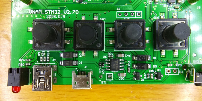
- 4 button + 1 encoder user interface
- Magnitudes:
- Resistance
- Reactance
- Impedance
- VSWR
- S11
- ESL (only in the single point measurement screen)
- Graphs:
- One marker
- Selectable range of frequencies
- Option to plot any magnitude (except ESL)
- Vertical scaling
- LiPo battery inside (3000mAh?)
The internal LiPo battery is big enough to use it for several hours with a single charge. That will let you take it to the field and forget about cables while testing. The screen is perfect for indoor use but it can be hard to see under direct sun. Also, always remember to avoid being near anything that could interfere with the reading and use anti-static ESD globes [Amazon] if possible.
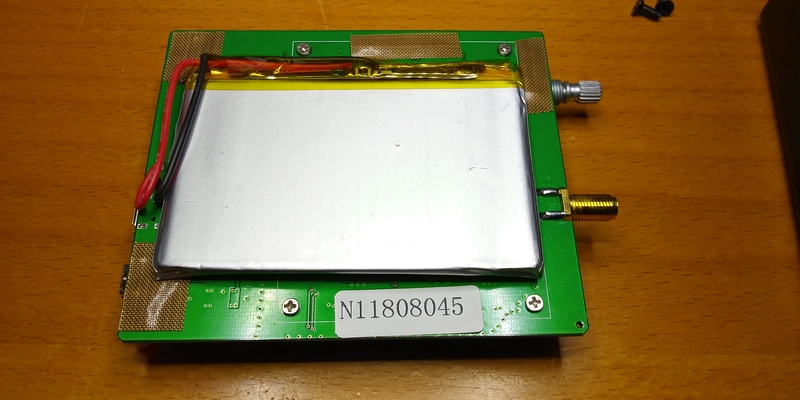
Sneaking inside
I cannot help it. And I guess a lot of you have the same “problem”. I cannot help tearing stuff appart to see what it hides inside. Sometimes I do it to see if I can add a new feature or sniff the information like in the case of the connected power meter. Other times I do it just out of curiosity. Here you have a few pics of the insides of the AAI NS1201SA.
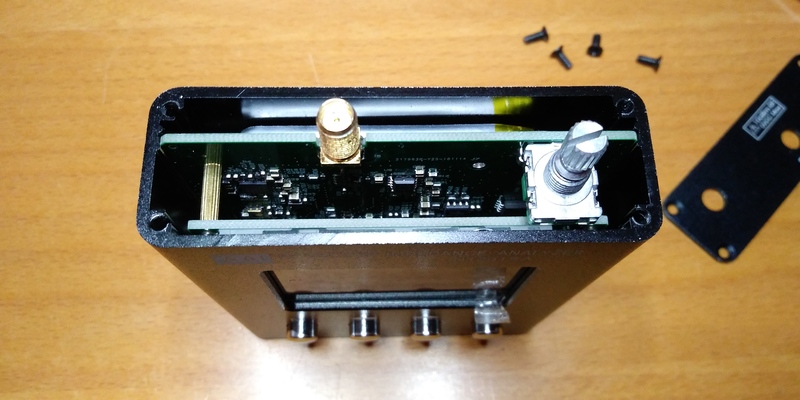
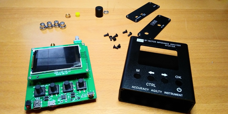
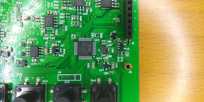
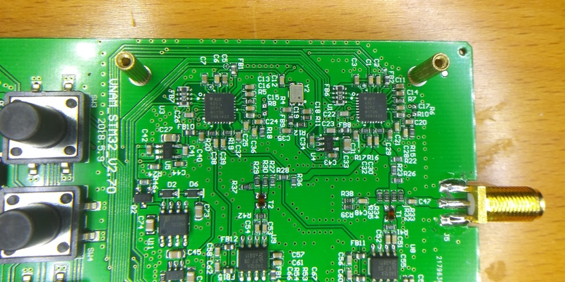
Main components:
- STM32F103 32 bits ARM microcontroller.
- ADF4351 wideband synthesizers.
- TP4056 battery charge manager.
A bit of theory
There are several metrics you want to know about an antenna. And often not all of them are easily available when buying it or even in the datasheet. You might be persuaded to look for the antenna with the biggest gain. But remember one of the first principles in science: energy is not created nor destroyed, only transformed. You cannot pretend an antenna (a piece of wire!) to radiate more energy than that you feed it. So a bigger gain simply means that the antenna radiates power only (or preferently) in some directions.
If you are aiming to a certain point then a directional antenna with a big gain will be great (terrestial TV antennas, for instance). But if you don't have a preferent direction, or maybe your sensor is moving or you are deploying a gateway and you want to listen in all directions, then you'll want an omnidirectional antenna that will probably have a gain of between 2 an 6 dBi.
But again, gain is not enough. You want the antenna to match the impedance of the transmission line. An antenna that matches the circuit impedance (50 ohms, for instance) is a well adapted antenna. The bigger the mismatch, the more power bounces back to your circuit instead of being radiated. And that extra power back into your circuit means that your sensor will not reach as far as it could but also that your electronics might suffer and eventually fail.
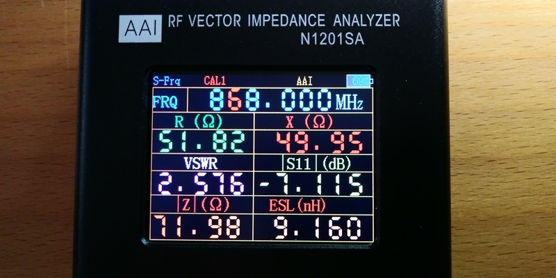
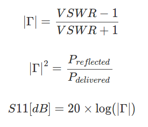
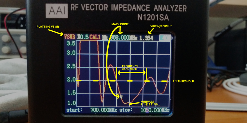
One magnitude that gives you an idea on how much power is bouncing back is the reflection coeficient represented by the greek letter uppercase gamma (Γ). This value is the ratio between the reflected power and the delivered power. It will be a number between 0 and 1 and you want it to be small and and as close to 0 as possible. The reflection coeficient is sometimes expressed in dB and named S11 (an S11 of -20dB is better than -10dB). An alterative way to express the reflection coefcient is the Voltage Standing Wave Ratio or VSWR. The relation between the two values is represented by the formulas and graphs below.
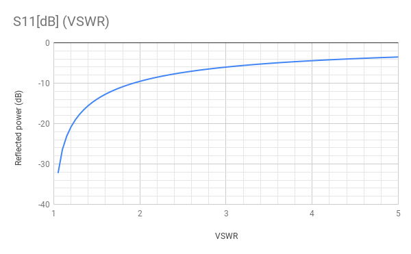
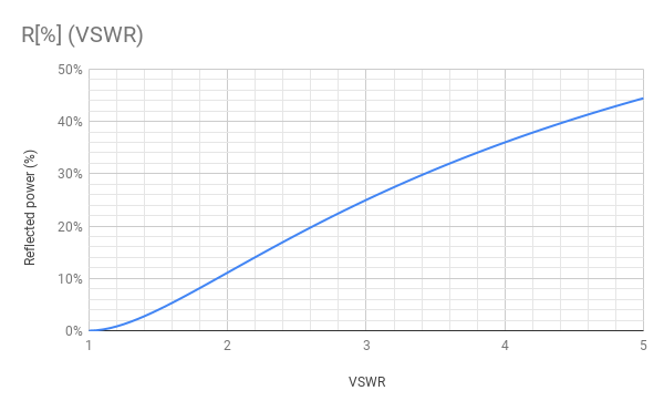
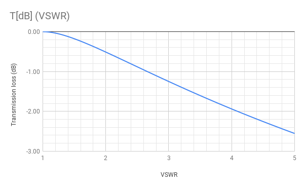
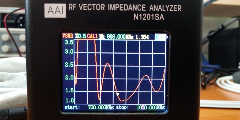
An antenna with 0 return will have a VSWR of 1 and from then upwards. It's a common convention to consider good values those below 2, which mean a reflected power of under 11% of the delivered power (you will see things as “<2VSWR” or “<2:1” in the antenna datasheets). Of course an antenna will have its resonance point at a certain frequency (sometimes more than one), therefore the VSWR will change along the sprectrum. We can also say that the frequency bandwidth of an antenna is the range of frequencies where the VSWR value is under 2.
Another very useful tool to calibrate the antenna and circuit is the Smith Chart. The N1201SA won't draw the chart for you but you can get all the data you need and use online tools to do your chart or calibrate the circuit.
A final note before the experimental data: VSWR or Γ are not the only values to take into account when choosing an antenna. You should also notice its impedance, resistance (some of the energy will be radiated as heat!) or even structural considerations, and of course gain and directionality…
If you want to know more about antenna specification, this application note by Linx Technologies is a great summary.
Antenna testing
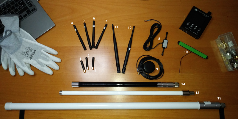
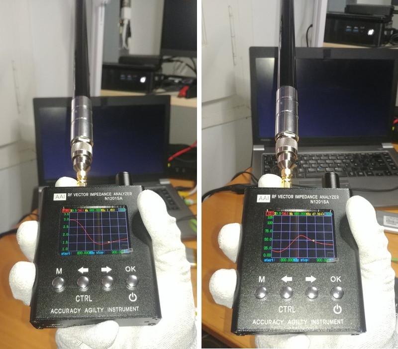
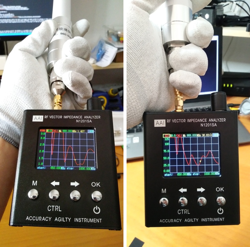
So I gathered some of the antennas I have at home and started testing them… I focused on the antenna nominal frequency (VSWR and Z) and frequency bandwidth (i.e. the range of frequencies where VSWR is less than 2:1).
868MHz antennas
First I evaluated the antennas that I'm using mainly for LoRa on 868MHz. They are not allways strictly 868MHz antennas but sometimes the manufacturer sells them as 868-915 antennas to target the european and north amercan markets.
| # | Description | Gain (dBi) | Connector | VSWR @ 868MHz | Z @ 868MHz (Ohm) | BandWidth <2:1 (MHz) | Price (€) | Link |
|---|---|---|---|---|---|---|---|---|
| 1 | Tiny black | Male SMA | 1.53 | 59 | 794-885 | |||
| 2 | Tiny black | Male SMA | 1.07 | 52 | 840-900 | |||
| 3 | Tiny black | 3 | Male SMA | 1.15 | 56 | 834-912 | 2.16 | Aliexpress |
| 4 | Small black elbow | Male SMA | 2.70 | 84 | - | |||
| 5 | Small black elbow | Male SMA | 3.23 | 77 | - | |||
| 6 | Small black elbow | Female SMA | 17.4 | 27 | - | |||
| 7 | Small black elbow metallic socket | Male SMA | 246 | 570 | - | |||
| 8 | Dipole patch | 2 | Male SMA | 1.17 | 56 | 770-957 | 4.71 | Aliexpress |
| 9 | Round patch IP67 | 2 | Male SMA | 1.34 | 38 | 783-1045 | 7.99 | Aliexpress |
| 10 | uFL dipole (Arduino) | iPEX | 2.85 | 18 | 894-950 | |||
| 11 | Medium black elbow | 5 | Male SMA | 2.03 | 42 | 868-961 | 2.76 | Aliexpress |
| 12 | Medium black elbow | Female SMA | 2.11 | 82 | 798-863 | |||
| 13 | 50 cm Wifx Outdoor Antenna IP65 (Lorix One) | 4.15 | Female N | 1.41 | 46 | 817-950 | ||
| 14 | 40 cm RAK Wireless Glass Fiber Antenna (old) | 6 | Male N | 1.28 | 48 | 830-950 | 30.20 | |
| 15 | 80 cm RAK Wireless Glass Fiber Antenna (new) | 5.6 | Male N | 1.36 | 41 | 853-954 | 50.05 | Aliexpress |
The first 10 antennas are meant for nodes (small or case mounted options) whilst the later 5 are bigger and maybe suitable for gateways or static receivers. Most of them perform pretty well except for the small black elbow antennas you can find almost everywhere. I'm not sure if the problem is with the antenna design or maybe they are worn out by usage, but some of the 6 that I have targeted the bin directly. I only kept 3 of them but not because they have good numbers but because they are not so horribly bad.
Update: antenna performance depends on a lot of different factors. After the initial post I noticed that the allegedly 5dBi elbow antennas perform significantly better when set at 90 degrees angle. The three I hvae threw VSWRs below 1.5:1, one of them showed a VSWR of 1.14 with an impedance of 56 Ohm at 868MHz.
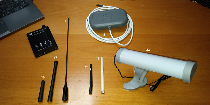
169MHz antennas
The second set of antennas I tested are the ones I'm using for the AllWize boards. The antenna is one of the critical points when using 169 MHz. On one hand, typical quarter length antennas would be 44 cm long for 169 MHz (!!) so we need really big antennas to get similar performances to other technologies. On the other hand, the small ground plane area compared to the carrier wavelength translates into worse performances.
Antenna matching is somewhat important here since maximum allowed transmitting power in Europe at 169MHz is 27dBm. That's 500mW while the maximum in Europe for the 868MHz band is only 14dBm or 25mW.
| # | Description | Gain (dBi) | Connector | VSWR @ 169MHz | Z @ 169MHz (Ohm) | BandWidth <2:1 (MHz) | Price (€) | Link |
|---|---|---|---|---|---|---|---|---|
| 16 | 2J0819-C708N | -9 | Male SMA | 2.29 | 46 | 169-174 | 1.38 | SOSElectronic |
| 17 | H169-SMA | Male SMA | 2.71 | 72 | 161-167 | 6.84 | SemiconductorStore | |
| 18 | Taoglass Meteor FW.80 | -3.91 | Male SMA | 1.96 | 76 | 169-172 | 16.46 | DigiKey |
The H169-SMA performance was poor. I certainly expected better VSWR values. The datasheet says VSWR <1.5:1 but it only get's that low ay 164MHz.
Wi-Fi antennas
Finally I tested some 2.4GHz Wi-Fi (802.11b/g/n/ax) antennas. Wi-Fi channels around 2.4GHz range from 2412 to 2484 MHz, so well within the possibilities of the N1201SA. Other bands (3.65GHz, 5GHz) are out of scope. Values below are for the 2.445GHz frequency point. Max transmitting power in the 2.4GHz band in Europe is 20dBm or 100mW.
| # | Description | Gain (dBi) | Connector | VSWR @ 2.45GHz | Z @ 2.45GHz (Ohm) | BandWidth <2:1 (MHz) | Price (€) | Link |
|---|---|---|---|---|---|---|---|---|
| 19 | White elbow | Female SMA | 1.16 | 45 | 2300- | |||
| 20 | Black elbow | Female SMA | 1.13 | 54 | 2300-2590 | |||
| 21 | Fon panel antenna | 7 | Female SMA | 1.34 | 44 | 2240- | ||
| 22 | Realtek RT8187L | 46 | Female SMA | 1.18 | 54 | 2410-2690 |
They have all performed really well!
Conclusions
Being able to profile an antenna is a must-have when you are dealing with RF. The N1201SA is an incredibly useful tool for the price it has and one of the best acquisitions I've ever done. If you or your community have the chance to get one to choose the proper antennas for your sensors or the receiver, do not doubt about it.
And about the antennas. Performance heavily depends on manufacturing procedure but not only. The values I got from similar antennas have been sometimes very different. That reinforces the utility of tools like the N1201SA since you will probably want to test the specific antenna you plan to deploy. A simple antenna analyzer is the first filter, next would be to measure how much power they actually radiate and in what directions. Do they really have the gain their manufacturers claim… I'd be surprised if those small whip 868MHz antennas really get the 5dBi. Let's see…
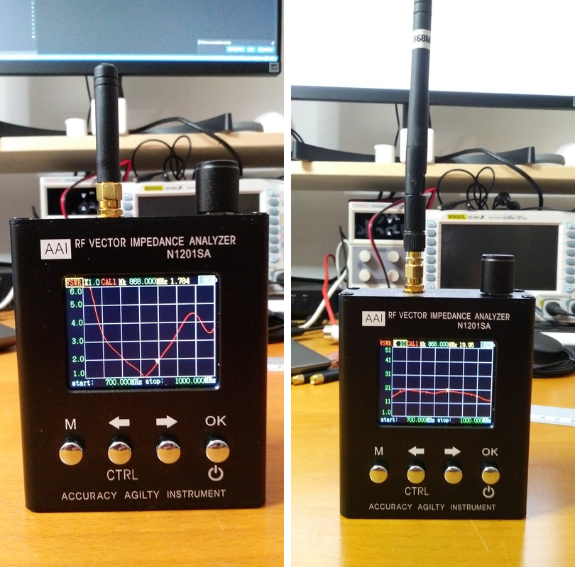
Gallery
And finally some pictures I took while doing the tests…
"Analyze your antennas using an AAI N1201SA" was first posted on 16 May 2019 by Xose Pérez on tinkerman.cat under Analysis and tagged aai, n1201sa, antenna, rak, vswr, relection, dbm, dbi, frequency, impedance, sma, ipex, type n, s11, toolbox, vna, resistance, reactance, smith chart, stm32f103, adf4351, tp4056, gain, directionality, bandwidth, wize.