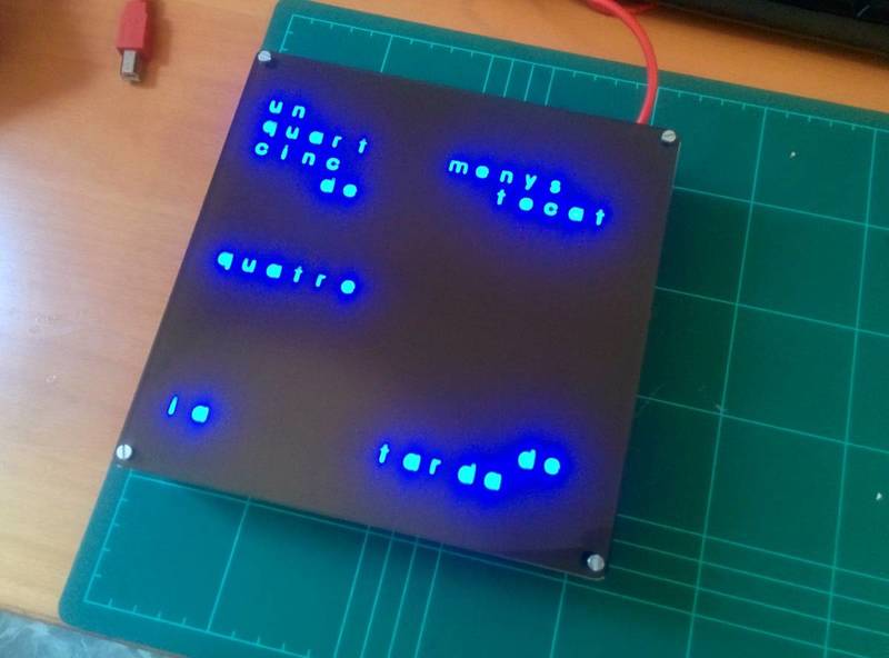
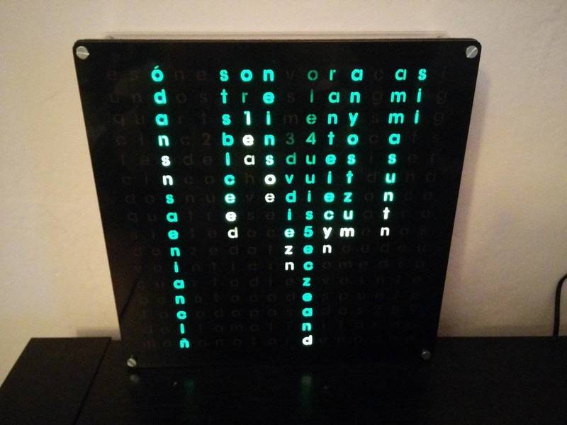
Wordclock with Green Matrix effect
Clocks are top projects for the maker community. There are tons of different ways to show or tell time. Or write time. Wordclocks are a subset of them by its own. You can find other wordclocks at instructables, for instance, or buy one from thinkgeek or from a local jewelry for just 450€. Mmm… well maybe that's a little bit on the expensive side…
Recently I've been doing things with clocks and WS2812 LEDs (a.k.a. NeoPixels). My interest started with Philippe Chrétien's Fibonacci Clock campaign at Kickstarter. I thought: “Wow! That's cool AND freaking freak! I want one”. But the $100 and the instructable he himself had done before about building your own made me decide to try it. Anyway, that's a different story.
That project led to this one. Because suddenly I happened to have 9 spare boards with an atmega328, an RTC, an SDCard slot, some nice buttons and the circuitry to drive a bunch of NeoPixels. I also happened to have a couple of LED matrices (you know, the kind of stuff you have in your bedroom drawer). So first I built a clone of the The Game Frame Pixel Art Project. It was great and my kids loved the pixelart. But I'm not going to talk about that project either.
The template
There are quite a few lessons from this project. Number one being that the most challenging task has been designing the template for the characters. On one hand I had a few requirements:
- It will have characters, not words, which means that each character has a LED behind it and it can be lit individually, the previous wordclock from thinkgeek is an example of what I did not want.
- Characters forming words will be together, no weird things like starting a word, the a gap, and ending it.
- It will have to have both catalan and spanish language in the same template. Actually this was unnecessary, I could have had one template for every language but in the initially I felt lazy about changing templates. Actually the constraints due to this requirement had proved to be an interesting puzzle to solve.
- Font should be clearly visible, and with no “holes”. Like the “O” being a simple circle. That meant finding a proper stencil font and playing with the tolerances of the laser cuter when working on cardboard.
First thing was to have a list of all the words I needed to fit in the 16x16 matrix. Now, there's something you should know about telling time in catalan in the traditional way. Basically you count quarters done to complete the hour, so “11:45” would be “3 quarters of 12”. You can use half quarters (“2 quarters and a half of 12” is “11:37”) and plus/minus five minutes (“11:35” is “2 quarters and five of 12”). The rest is fuzzy: almost, touched (meaning “due”),… And finally you have to say whether you are in the morning, evening or night. In spanish is more straight forward. Of course, even after some word engineering, some words just did not fit, but the overall template is really complete.
Choosing the right font
Next was the font type. After some testing I decided to go for the “AG Stencil” font. I created the 2D models in OpenSCAD using the “offset” command to play with the borders of the font. I wanted them to be as small as possible, but big enough so the laser cuter would not join the lines and cut holes in the stencil.

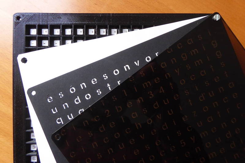
The sandwich
To box the project I went for a simple approach, based on the Pibow cases for the Raspberry Pi. The idea was to do a sandwich of layers. These layers are from front to back:
- A smoked acrylic plasting, 4mm thick, laser cut. Is transparent but black enough to hide the underneath characters from almost any angle except direct sight.
- The character template, laser cut in black cardboard.
- A simple white paper as diffuser.
- A 3D printed grid to isolate each pixel.
- The LED matrix from ebay.com
- A transparent acrylic plastic, 4mm thick, laser cut, as support.
- 4 stand-offs
- The last transparent acrylic plastic, 4mm thick, laser cut, with holes to attach the PCB and to hang it on the wall.
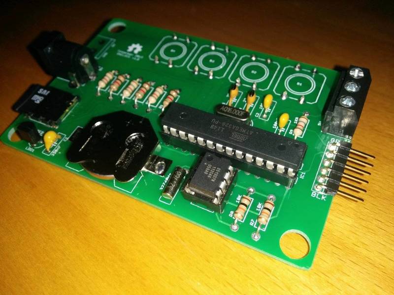
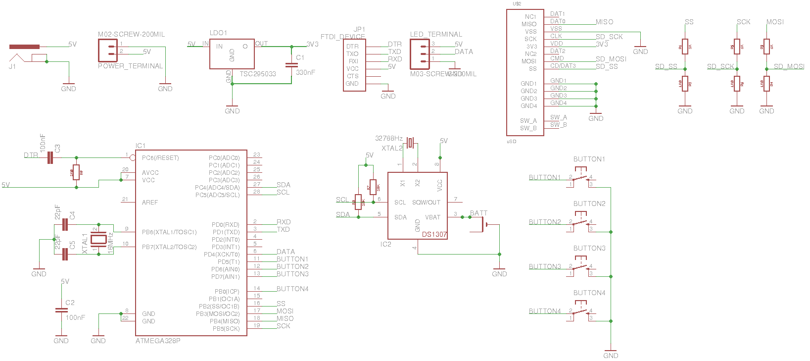
The board
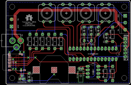
I designed the board so I could use it for different projects: the Fibonacci Clock, the WordClock and the PixelArt display. Most of the elements will be used for every one of them (albeit somewhat differently) but other wont (no need for SD support in a clock). It can be powered with 5V via a 2.1x5.5mm barrel plug or a screw terminal, there is an FTDI-compatible header to program it and a 3-wire screw terminal to connect Neopixel-like strips.
The board in the picture is version 1.0. There were some errors with the TSC2950 3v3 regulator (the footprint was flipped) and the SD Card slot (I swear I reviewed several times the connections, but still). Those problems are solved in version 1.2, although they basically affect the SD support, something this project does not use. You can check out the schematics for Eagle in my Fibonacci Clock repository in Bitbucket.
I have a version 1.3 in mind adding a capacitor across the power lines in the LED matrix connector and replacing through hole components with smaller SMD ones, and maybe some other changes.
It's not the first board that I send to fab to smart-prototypes.com. A 10x10cm 2 layers board, lead free, 1oz copper 100% e-tests costs $16.90 ($5 less if you don't care about lead, but you should). Shipping will depend on the total weight but I've paid as little as $5. The quality is great for cheap green boards and the have a decent processing (5 days) and delivery times (about 15 days to Barcelona).
The code
The code is free source, GLPv3 licensed and available in the my Wordclock repository in bitbucket. In the repo you can also find the OpenSCAD models and the TTF font I used.
The code to show the time is pretty simple. The different buttons allow you to change the mode (from normal clock to matrix-effect clock and back), the brightness and color of the characters (when in normal mode) and the language (spanish/catalan). Holding the mode button pressed you can change the hour and minutes with the middle two ones. The configuration (current mode, language, color and brightness) is stored in EEPROM. The time in the RTC backed up with a CR2032 battery.
The current mode is managed by a simple state machine but the interesting part is the matrix pattern. There is a language definition file for every language that defines what LEDs have to be lit to form a certain word (sometimes more than one word like in “son las”). This words are coded in a tupple with the row number and a 16bit number for each LED in that row. So, for instance, the word “tarda” (afternoon) is:
#define CAT_TARDA {14, 0x001F}
meaning “lit the 5 right-most LEDs in row 14”.
And then there is a second file to calculate the syntax of the time telling: what words have to be activated to tell the current time. This is very language-specific but I tried to abstract common elements like plurals and repetitive patterns.
The main loop checks for buttons presses and calls the update method depending on the mode. In normal mode every time the minute changes the current language pattern is loaded in a buffer and translated into actual LED positions since this LED matrix follows a snake pattern: first line is LEDs 1 to 16, next is LEDs 32 to 17 (backwards), next is 33 to 48,… and voilà.
Enter the matrix
The final touch was to add a fancy green matrix effect, very much like in the movie except for the fact that each digit is always the same. You have seen it in the video above. Here I entered the world of memory optimization since I had to store beams positions, lengths and speeds, hold current time pattern and lit ni yellow only those characters already “hit” by a beam. After some playing the result looks nice, although it works better if you look at it from a certain distance.
"Wordclock with Green Matrix effect" was first posted on 26 May 2016 by Xose Pérez on tinkerman.cat under Projects and tagged atmega328, clock, matrix, neopixels, rtc.