The ESPurna board, a smart wall switch with power monitoring
If you have read me, you might know I have a firmware for ESP8266-based smart switches called ESPurna. The firmware integrates with Alexa, Domoticz, Home Assistant and about any other service that supports MQTT or HTTP REST APIs. It supports a variety of devices, including almost the whole Sonoff family by Itead Studio, but also some other commercially available boards and light bulbs, and open source hardware projects as well.
But sometimes you just don't find the proper hardware for your specific case. Maybe it doesn't expose enough GPIOs, maybe it's short of analog ports, maybe you need a double-throw relay,… Sometimes we manage to work around these limitations of the hardware adding peripherals or using a thin iron tip. But other times the problem is that it just doesn't fit.
And size was the main reason I started creating my own smart switch board.
The ESPurna-H board
So the ESPurna board was born, and it got the shape of my home wall switches: 50x50x20mm. Also, I added some features that I have missed in some boards or liked from others:
- SPDT 10A relay with NO and NC connections brought out
- Connections for external button and notification LED
- Optical isolation between the logic circuit and the relay circuit
- HLW8012 chip for power monitoring
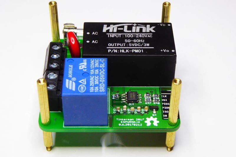
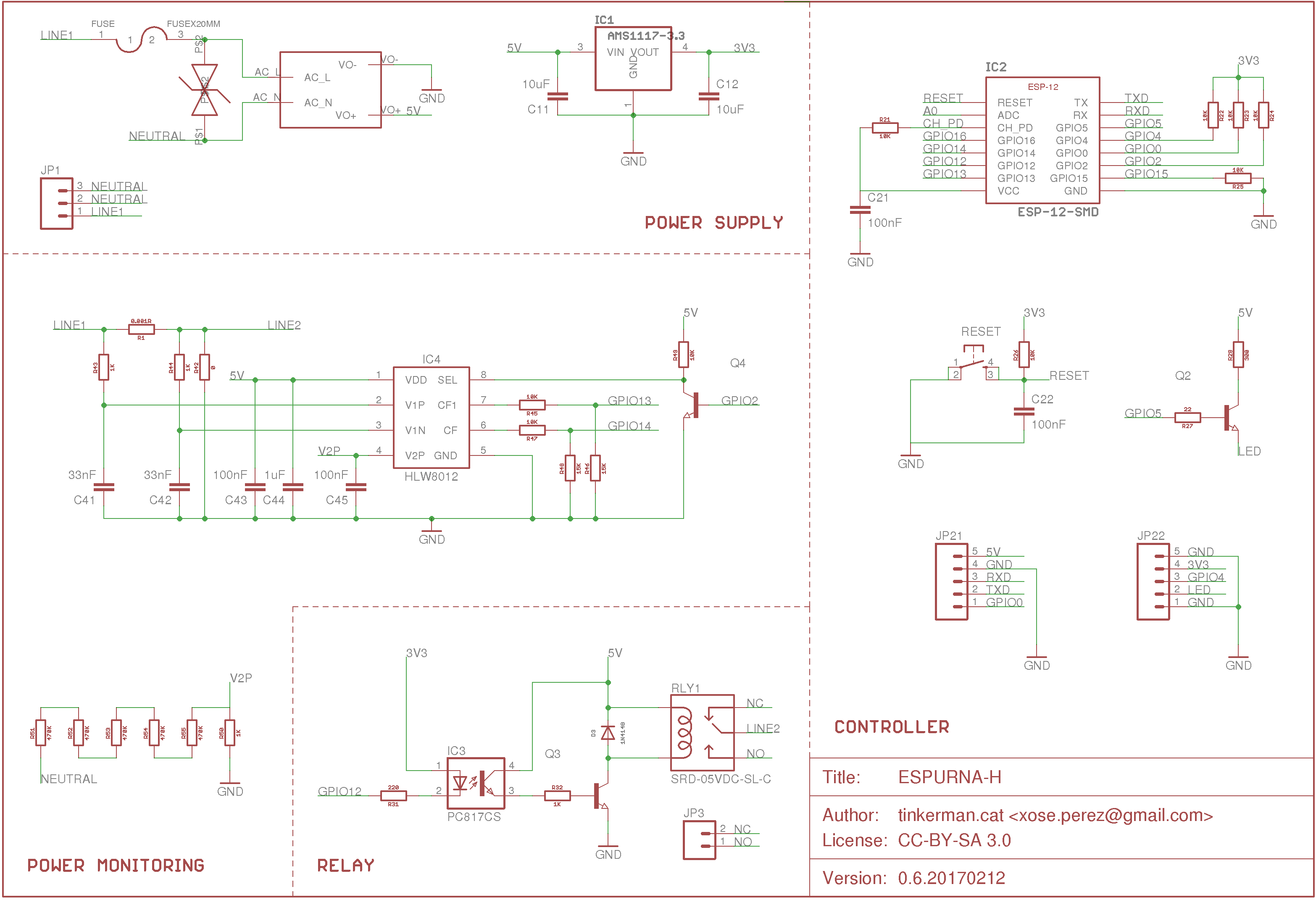
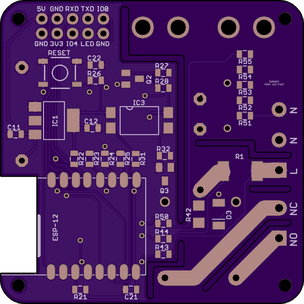
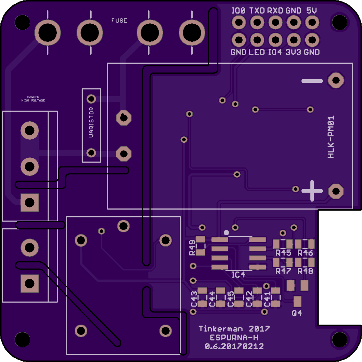
The board uses the Hi-Link HLK-PM01 (Aliexpress) AC/DC that outputs 5V to up to 600mA from an 100-240VAC source. So the board is usable anywhere in the world. There are cheaper options but this one comes encapsulated and has very good reviews. Just before the transformer there is a crystal fuse in series and a varistor across input terminals. I'm also using the trustee Songle SRD-05VDC-SL-C (Aliexpress) single pole double throw relay that supports up to 10A current. The board brings out both normally open and normally closed terminals of the relay, which is very convenient when using it with multi-way switches. The relay is switched by a 2n7002 N-channel mosfet isolated from the controller by a PC817C optoisolator.
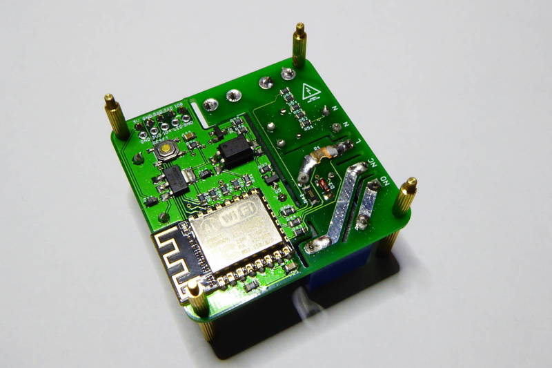
The controller can be any ESP12 module, in the pictures it is a ESP12E module by Ai-Thinker (Aliexpress). An AMS1117-3.3 (Aliexpress) does the step-down phase to power the ESP module, there is also a RESET button and a 2x5 header with the programming GPIOs and two connections for external button and LEDs.
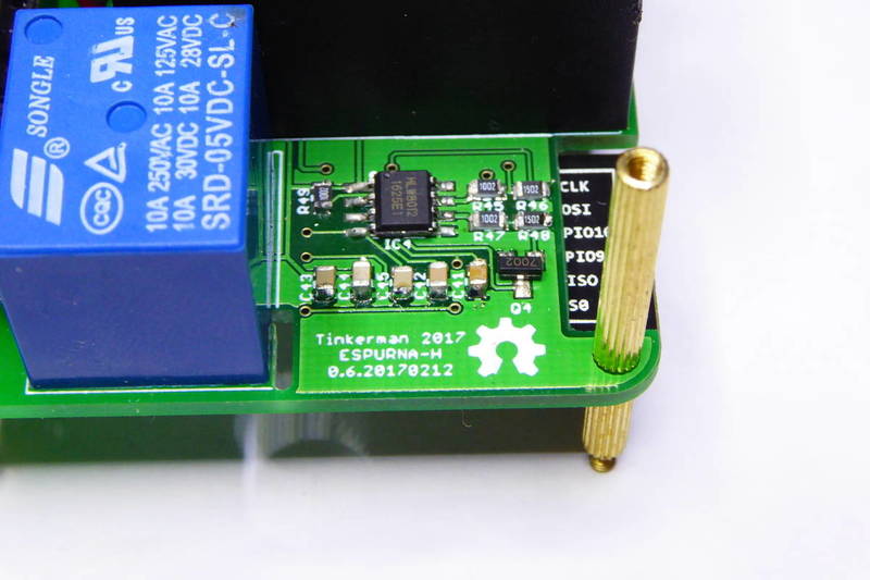
Finally the board is ready to add power monitoring circuitry based on the HLW8012 (Aliexpress), the same IC the Sonoff POW uses. The schematic is the same as in the POW, with a 1 milliOhm current sensing resistor and a 2350:1 voltage divider to monitor the AC voltage.
The HLW8012 requires that the power line should be tied to the circuit ground. This means that you should never ever connect the board to your computer while connected to mains. Never ever flash the board while connected to mains!
Open source hardware
The ESPurna-H board is released under the Creative Commons Attribution-ShareAlike 3.0 Unported License (CC-BY-SA 3.0) and follows the terms of the OSHW (Open-source hardware) Statement of Principles 1.0. It can be checked out at my ESPurna board repository on Github.
You can use the latest gerblers from the repository or open the project using Eagle +8.0. You can also order the board directly from OSH Park clicking on the link below:
Please note that you will be using this board at your own risk. This product is meant to be plugged to mains and it requires a deep understanding of the perils of it. I disclaim any responsibility, risk, liability and damages arising out of death or personal injury resulting from assembly or operation of this product.
Interface
The board is ready to use an external switch or push button to trigger the relay. But I wanted to keep as much as possible of the original switch enclosure and I didn't want to drill any holes on it.
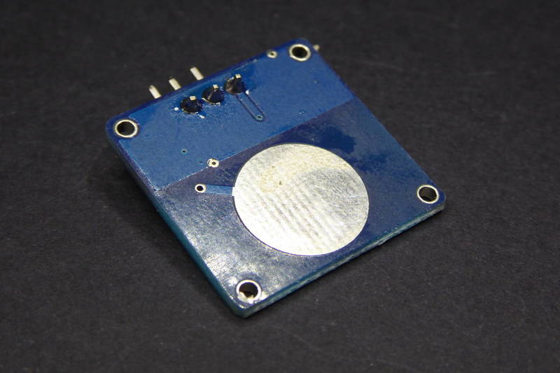
So I started doing some tests with touch sensors like the one below. This one is a TTP223B Module Capacitive Touch Switch (Aliexpress) that sells for less than a euro shipping excluded. The sensor board fits tight in the back of the front plate of the switch and it “feels” the contact across the plastic just fine.
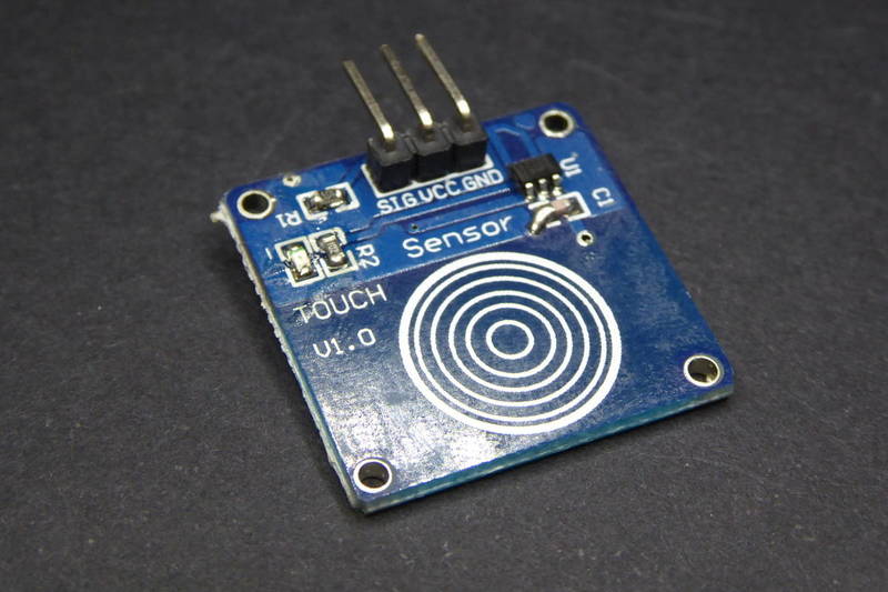
The switch is easy to configure from the ESPurna firmware, just define it as a BUTTON_PUSHBUTTON with no pull-up since it's a normally low sensor.
// -----------------------------------------------------------------------------
// ESPurna
// -----------------------------------------------------------------------------

#elif defined(ESPURNA_H)

    #define MANUFACTURER        "TINKERMAN"
    #define DEVICE              "ESPURNA_H"
    #define RELAY1_PIN          12
    #define RELAY1_PIN_INVERSE  1
    #define LED1_PIN            5
    #define LED1_PIN_INVERSE    0
    #define BUTTON1_PIN         4
    #define BUTTON1_RELAY       1
    #define BUTTON1_MODE        BUTTON_PUSHBUTTON
    #define ENABLE_POW          1
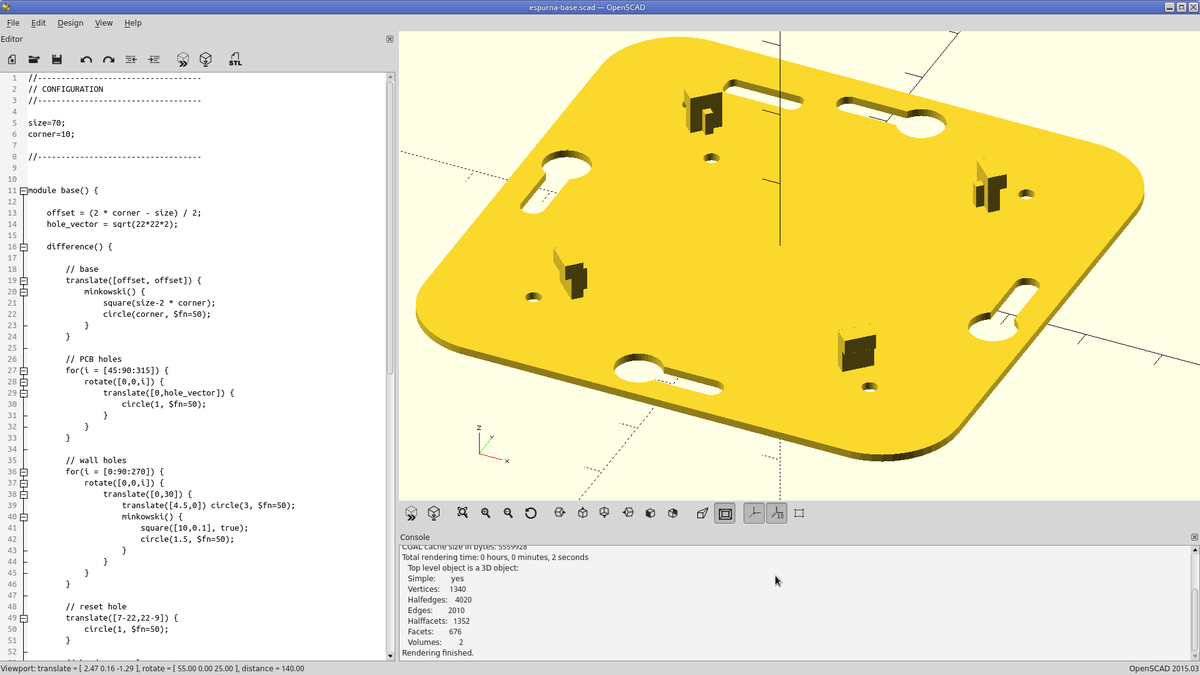
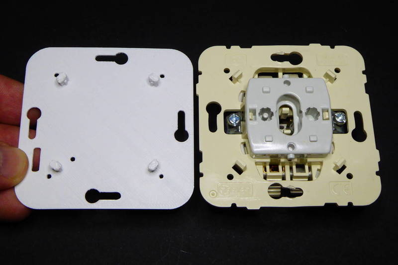
Wall switch base
Another issue I had to solve was how to replace the inner mechanism of the switch with the ESPurna board so it stays put in place. The switches have a plate that is tighten to the wall switch enclosure and fixes the mechanism of the switch. The same plate has 4 pegs that clamp the switch bezel.
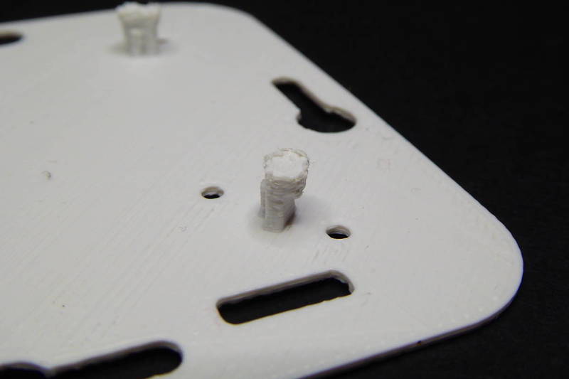
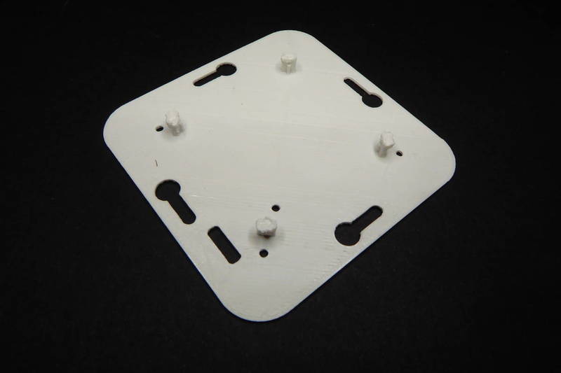
I decided to test doing a 3D printed plate with the same dimensions and functionality, holes to screw it to the enclosure, holes to screw the ESPurna board behind it and the pegs for the bezel. I also added a hole to reach the reset button and a window for the cables for the touch sensor and the LED.
Installation
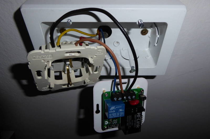
Once everything was ready the first installation was easy peasy. One important requirement is that you need to have both line and neutral wires on hand to power the board. Some switches only have one of them.
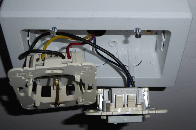
In this case I had a plug and a switch on the same enclosure. I used the cables powering the plug to power the ESPurna board.
The enclosure with the bezel in place. The 3D printed part keeps the hot zones out of reach and the ESPurna board safe and fixed behind it. The touch sensor is fixed tight in the back of the front plate. The two remaining cables are for the LED but I finally decided not to add it.
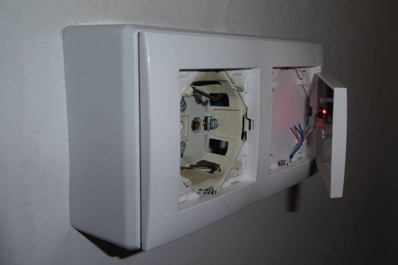
This version of the 3D printed plate does not have the pegs to keep the front plate in place, so I decided to hot-glue the corners. It will be easy to remove and the final result is almost unnoticeable.
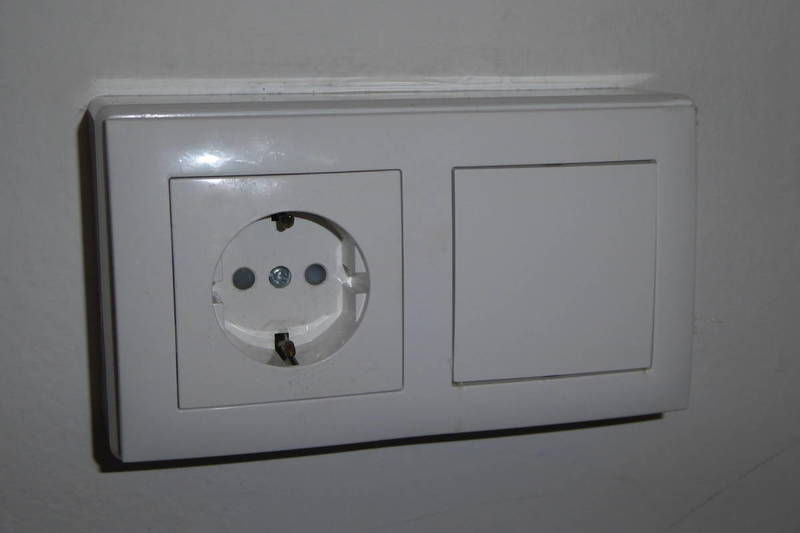
The main difference between the original switch and the modified one (aside for it being “smart”, that is) is the user experience. Originally it was a normal two-position switch with the classical “click” feeling. Now it's a touch switch. The touch sensor works great but it requires about 500ms contact to switch. It takes some time to get used to it. But of course you can always ask Alexa to toggle it for you ;-)
UPDATE: Check also another project based on this board, the ESPurna Smart Socket, same features, but “portable” :)
"The ESPurna board, a smart wall switch with power monitoring" was first posted on 07 April 2017 by Xose Pérez on tinkerman.cat under Projects and tagged 3d printing, alexa, ams1117, esp12, esp8266, espurna, hlk-pm01, hlw8012, open hardware, openscad, optoisolator, oshpark, songle, sonoff, touch sensor, ttp22eb.