You might have heard about The Things Network (TTN from now on) here or somewhere else. If you have not, then it's a good opportunity to visit the project and check if there is a community of users around you. I have been a core member of the TTN Catalunya community for over 2 years now. This year we are working hard deploying several new gateways in Barcelona and doing workshops and hackathons with the main goal of helping individuals and social entities to carry out projects around a LoRaWan open, libre (free as in freedom) and neutral telemetry network.
One of the original goals of the TTN project was to reduce hardware costs so more people could afford buying (or building) their own gateways, add them to the network and help it grow. The 1500-ish € Kerlink (and similar) gateways were out of scope for most of us but a 300€ alternative is much more interesting.
The TTN Gateway was crowd-funded on a successful KickStarted campaign. Truth is they have struggled to deliver the devices. They started shipping almost two years after the end of the campaign (mine arrived only 2 months ago). But even thou, the project has had a lot of media impact and other manufacturers (some of them, big players) have decided to provide different price range solutions, including low cost, DIY ones. IMST released its iC880A concentrator and a few weeks after there were instructions on how to use it with a Raspberry Pi and soon after an adaptor board for it. This year Chinese manufacturer RAK Wireless released the RAK831 concentrator and a special kit to connect it to a Raspberry Pi also. Both IMST and RAK are also selling cases and antennas so you can build your own “testing” gateway for under 200€, less if you happen to have a spare Raspberry Pi at home, which you probably have.
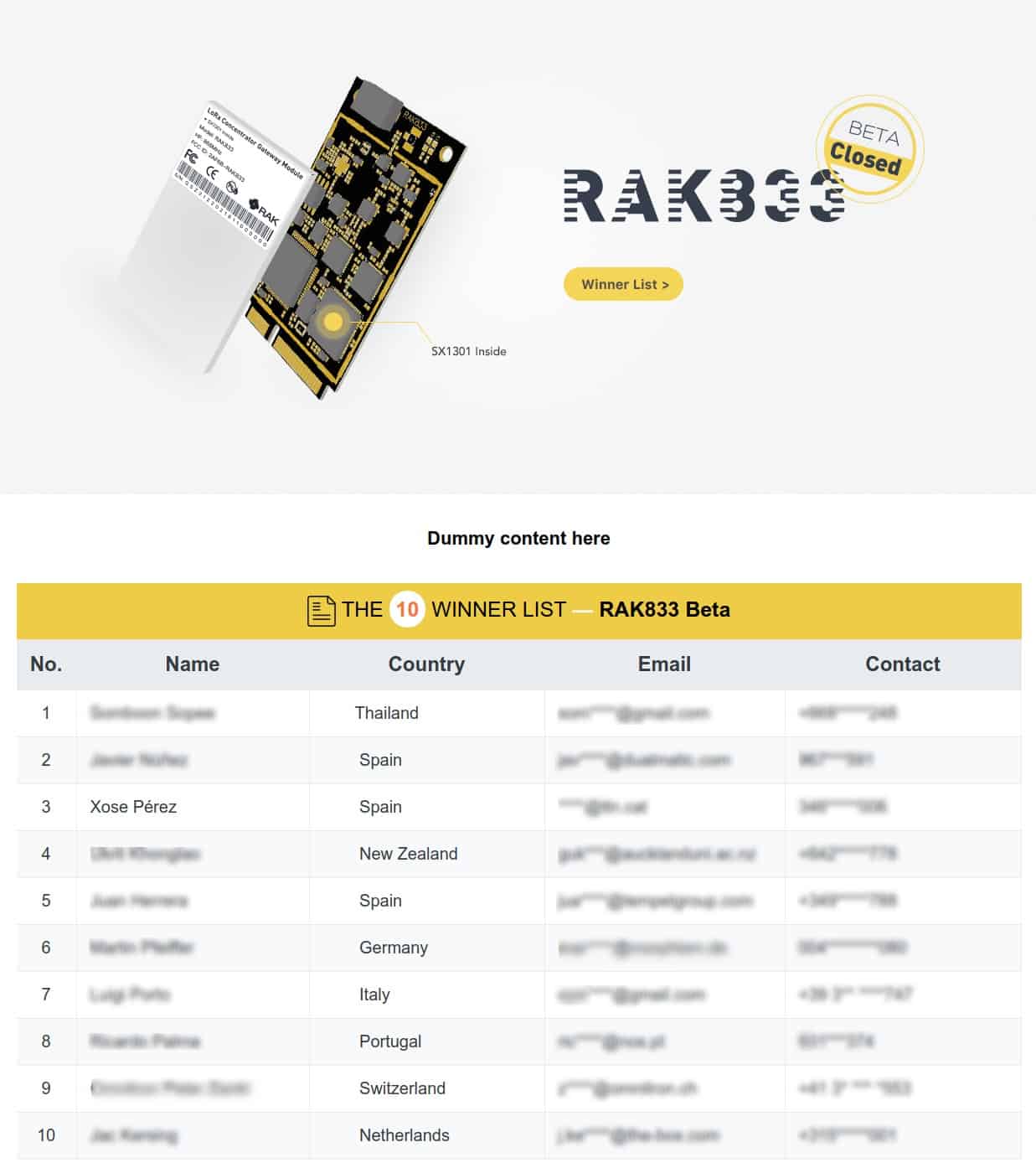
So we all expect this to go further. It looks obvious that Microchip will start selling the MiniPCI-E concentrator in the TTN Gateway sometime soon. But in the meantime, RAK again has taken advantage and opened a beta-testing program for their new RAK833 board…
How it all began
I read the post at the TTN forum about it two months ago. The device was on sale (absurdly expensive at the moment, normal with Aliexpress pre-releases) but at the same time it was flagged as “beta” and there was a “beta-tester” program on the go. You are right, this is just marketing, but I couldn't help giving it a try. So I applied with the idea of reproducing the same pattern as above: designing a Raspberry Pi hat where you could mount the RAK833 MiniPCI-E board and adapting the gateway code and packet forwarder to work with it.
And you know what?
The project
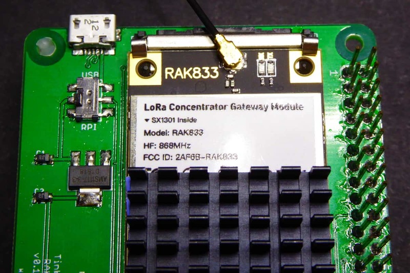
Of course, I had taken a look at the RAK833 datasheet [PDF] before submitting my proposal. The module has the common SPI interface to the SX1301 inside and a USB interface via an FTDI2232H chip. It should be straightforward to wire it the same way the iC880A and even use the same setup.
The only concern I had was the MiniPCI Express connector. I had no experience about it and even less on how to solder those small pads… that'd be a challenge.
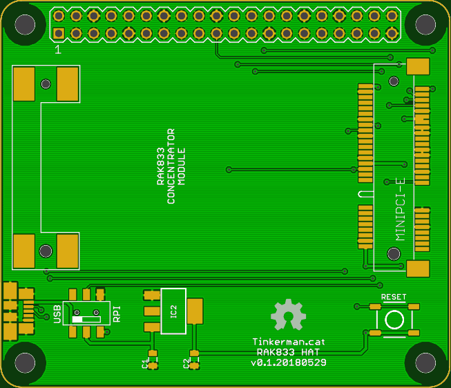
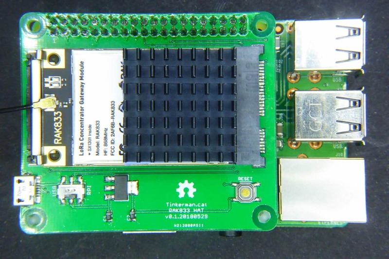
My first design considers both interfaces (USB and SPI) and it's not 100% compatible with the Raspberry Pi Hat specification (no slid for the camera connector, no EEPROM). The module is connected to the SPI0 interface in the Raspberry (NSS/CS to CE0) and has a DPDT switch to change from the SPI interface to the USB.
My next iteration will probably remove the USB interface. It makes no sense in this board. If it's a Raspberry Pi Hat then it's meant to be used with a Raspberry Pi via the SPI interface. Besides RAK sells a very cheap MiniPCI-E to USB board so there is no advantage in having both interfaces in this board.
A parcel from PCBWay
Seeedstudio has been my usual fab for the last year more or less. But this time I wanted to try PCBWay, since I had been told only good things about them.
My first problem was that I couldn't find any design rule files for their service so I just used the ones I had for Seeed. Then I submitted the design to both Seeed and PCBWay to compare the services. The price difference was insignificant but soon I noticed the first difference.
It's something I'm not used to. PCBWay does a manual revision on all orders and does not proceed with the order until it has been approved. If you think about it that can be pretty cool. I had had problems only once (with OSHPark). It was not their fault but the problem could have been easily detected by a human.
And there was actually a problem with the design. I initially chose a black mask and apparently, the minimum distance between traces they can handle is different from black to green. My design was OK if using a green mask but they couldn't do it with a black mask. “Do it green then”.
A couple of weeks after, the mail woman handed me a parcel with a nice box from PCBWay while I was having a coffee at a bar near home (this kind of things happen if you live in a small town). One week from order to delivery. Not bad at all. Next time I will go for a cheaper shipping thou.
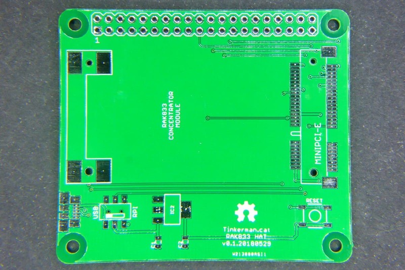
The boards looked great. Good quality mask and silkscreen. Centered pads. No noticeable glitches. I was very satisfied.
Next step was soldering the components I had just received from Mouser.
The PCB schematic and layout for the RAK833-hat is released under the CC-BY-SA-4.0 license as free open hardware and can be checked out at my RAK833-Hat repository on GitHub.
Another parcel from RAK Wireless
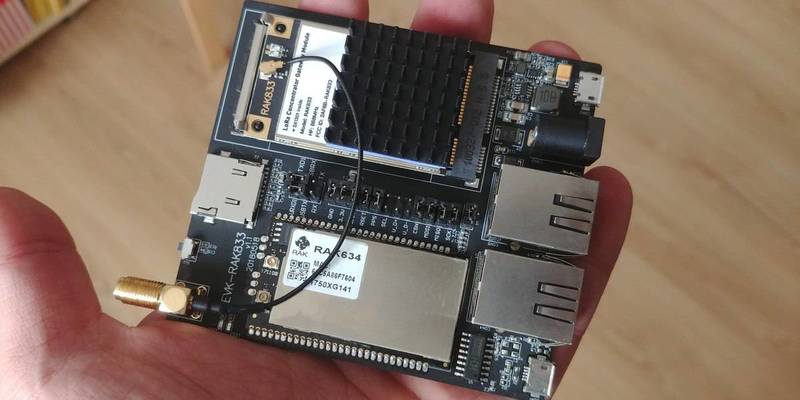
The project sat waiting on the Inbox for 3 weeks until I actually received the RAK833 Evaluation Board. I was only expecting the MiniPCI-E board but instead, I received the whole evaluation kit. I must thank RAK Wireless for their generosity.
The RA833 Evaluation Kit (EVK-RAK833 or RAK833-EVB depending on the document) is a full routing solution that uses the RAK634 [PDF] wireless router module based on the MT7628N. The RAK833 Evaluation Kit [Aliexpress] is selling for around 150€. The SPI-only version of the RAK833 [Aliexpress] module costs 86€ but the SPI&USB RAK833 [Aliexpress] is 17€ more expensive.
I had a moment of doubt. Why would I try to use the RAK833 module with a Raspberry Pi if I already had a full gateway? Well, the first reason to keep going was commitment, but there were also other good reasons to have a Raspberry Pi-based solution: the ubiquity of Raspberry Pi boards, ease of use, community, and price.
I will not review the Evaluation Kit in this post, maybe in a future one. Now I will focus on the RAK833 module and how to make it work with a Raspberry Pi.
The RAK833 module itself is really small. Just 50x30mm, that's 3.5 times smaller than the iC880A (80x67mm). It is true that the MiniPCI-E interface is not that easy to use, with the iC880A you can start by connecting dupond wires between the Raspberry PI and the concentrator (not a good idea on the long term, wires double as antennas and some people has experienced random resets).
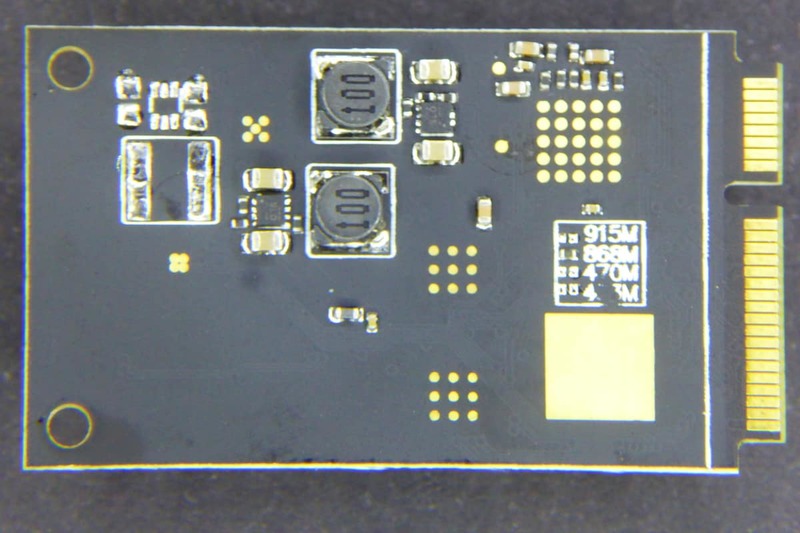
Two more things to notice: the dissipator and the frequency selector. The module really gets hot. You cannot touch the dissipator with your finger for more than a couple of seconds. That's about 45 degrees Celsius minimum on the dissipator. Also, on the back of the board, there are 4 pads to select the frequency. It looks like placing a 0Ohm resistor in the right place is the only thing you have to do to use a different carrier frequency.
Solder time
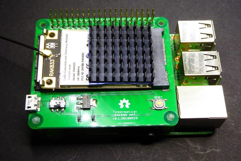
About the same day I received the PCBs I had also received a parcel with the components. In the repository, you can check the Bill of Materials. Let me just comment here a couple of choices. The Molex MiniPCI-E 4.0H connector was the one I found with a matching latch to hold the MiniPCI-E board in place.
The regulator is an AMS1117-3V3 and it's fed via the 5V line of the Raspberry Pi or the USB connector, depending on the position of the DPDT switch. I have a stock of them so it's my default choice for a 3V3 power source. It output up to 1A, far more than the 260mA the RAK833 module requires as per datasheet. A reset pushbutton (useful if using the USB interface) and a Molex microUSB connector complete the BOM.
My biggest concern was soldering the tiny pads of the MiniPCI-E interface. I started horribly bad, bridging the first to pins. So I decided to flood it in flux and it all went better except for the ground pins which are always harder to heat.
The only design issue was that I somehow wronged the switch footprint. Pads were a little closer than the switch I had but still, I could solder it without a problem. Also, the small fixation holes in the middle of the footprint were too small for the plastic legs in the switch so I just cut them off.
It really can't be this easy…
Next step was making it work. I wasn't expecting much trouble here but it really was too easy. I used the installation script for the iC880A that Gonzalo Casas (@gnz) and the TTN group at Zurich has in their ic880a-gateway repository. There is a copy of that script in my RAK833 repository, with the few changes required to make it work, it basically does:
Use the SPI branch of the ttn-zh repository
Keep the native SPI mode in the library.cfg file
Remove non-needed FTDI rules
Add a custom rak833_spi.h file in the lora_gateway project to display a proper name
You only have to prepare an microSD card with the latest Raspbian image (I personally used the Stretch Lite version), enable SPI using the raspi-config tool and run these commands from a terminal:
git clone https://github.com/xoseperez/rak833-hat.git
cd ~/rak833-hat/install
sudo ./install.sh
The script will output a EUI based on the ethernet interface. Register a new “legacy” Gateway in the TTN console using that EUI and…
That was easy!
The installation script is released under the GPL-3.0 license (as the original work by Gonzalo Casas) and can be checked out at my RAK833-Hat repository on GitHub.
A harsh competition
First things first: I'm not a radio expert and I don't have the proper tools to compare two gateways.
With that said, I prepared the iC880A-based and the RAK833-based gateways with an as much as possible similar setup. Both on my office window with the same antenna type (a small ~2dBi monopole) and similar “visibility”. Now, my office window is probably the worst place in the world to place an antenna. It's a first floor in a small town with narrow streets and rock on the back of the building. I didn't pretend to reach very far away with this but again my goal was to compare how the two gateways performed.
So I just started walking with my M5Stack LoRa node (at SF7BW125) and my phone with the TTNMapper application, clicking every now and then to send a test message. I already knew I would have some success all along the seashore from the breaker on the north to the river on the south, about 500m one from the other. I also knew I would hardly get any hit when going uphill.
In total, I recorded 70 different points at SF7BW125 (I actually sent several more but those were recorded by at least one of the gateways), parsed the (pseudo-)JSON file the TTNMapper app generates and did some graphs.
SF7BW125
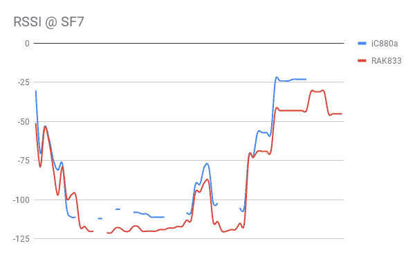
Again, I'm not an expert. But the results are kind of odd. The receiver with worse RSSI values (the RAK833) actually received a lot more messages…
The RAK833 gateway got 68 messages and the iC880A only 46.
The RAK833 reported consistently lower (worst) RSSI values for each hit. I'm not sure what this means.
The RAK833 recorded messages down to -121dBm whilst the iC880A only reached -112dBm. Again, not sure this is relevant, see the previous point.
The RAK833 seemed to perform better on bad SNR environments.
Since these results make little sense I tried at a different data rate (SF12BW125) and also swapping the antennas to remove the effects of a malfunctioning antenna.
SF12BW125SF7BW125 swapping antennas
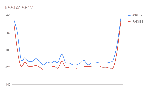
So for the second and third runs, results were quite different:
The iC880A gateway got a few more messages than the RAK833
The RAK833 again reports lower RSSI values (it's not the antenna, then).
The lowest RSSI for RAK833 was -123dBm, -118dBm for iC880A
For all those radio engineers out there, please forgive me if this makes no sense.
It's hard to get any conclusions from these values. The different RSSI values could be a different algorithm to calculate the RSSI (some radio chips can be configured to use different RSSI calculations) or a bad solder joint in the antenna path. My first test at SF7 showed that the RAK833 got significantly more messages than the iC880a but I could not reproduce this result in the second or third tests where the iC880A actually got a few more than the RAK833. The RAK833 datasheet states the concentrator has an RX sensitivity of -136.5dBm at SF12, but mine did not get close to that.
I will appreciate any advice on how to interpret these results or improve the test procedure (without having to buy expensive tools).
Conclusions
The RAK833 module by RAK Wireless is a very good choice to build your own gateway and a good competitor for existing solutions. Performance looks better at lower SF and slightly worst at high SF than that of the IMST iC880A module, but you should take this statements with a grain of salt.