Power monitoring with Sonoff TH and ADC121
Lately I've been quite busy with the ESPurna firmware. It's growing bigger and gaining some momentum. It's really fulfilling to see other people using it and reporting back. But at the same time it's very time consuming. Last Saturday I released version 1.5.0 with some new functionalities and bug fixes and I decided to use some of my free time over the weekend to work on a project that's been waiting for a month in the shelf.
A few weeks ago I was playing with the Sonoff TH and I wrote a post about its sensor interface and the possibility of using lots of different digital sensors, including I2C sensors since the board can be easily hacked to export 2 digital pins over that interface.
And having I2C not only increases the number of potentially usable sensors but also opens the possibility of using I2C Analog to Digital converters to overpass the lack of analog inputs in the device. Here it comes the Texas Instruments ADC121 (datasheet), an 12-bit precision ADC with I2C support priced 2.74€ in quantities of 1.
Hacking the Sonoff TH
In my previous post about the Sonoff TH I already mentioned what to do to export a second GPIO in the 2.5mm jack output. It's really simple, a 0Ohm resistor to bridge a pad (or a blob of solder) and a pull-up resistor if you plan to use it as I2C.
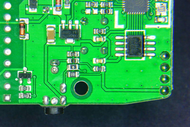
The think that puzzles me is that the pads for those 2 resistors are already there, but unpopulated. Obviously the engineers at Itead Studio designed a connector with 2 digital GPIOs but during the manufacturing it was decided to leave only one accessible. After all Itead is selling 2 sensors for the TH that both use just one digital pin, so I guess it was a money-driven decision, but still… it's only two more resistors!
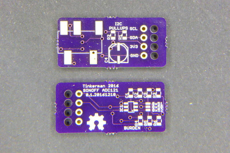
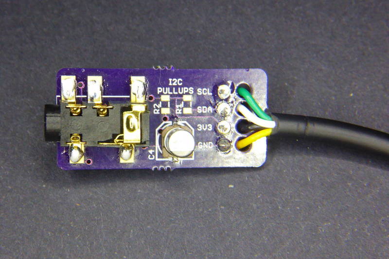
ADC121 board with connector for a 3.5mm CT jack
The idea was to have a small breakout board with an ADC and a more standard 3.5mm jack, the same size most of the non-invasive current clamps out there use. I decided to do a board with a single channel ADC121C027 by Texas Instruments.
The decision on what ADC to use was between the ADS1115 [Aliexpress, module] I already had experience with and the ADC121 family, specifically the ADC121C021 [Aliexpress] in VSSOP package and the ADC121C027 in SOT package. The ADS1115 has 4 16-bit ADC channels (or 2 differential) and 4 hardware selectable possible addresses. The ADC121 on the other side is a single channel 12-bit ADC with 3 possible I2C addresses. But they are half the price…
Since the goal was to create a current sensor compatible with the Sonoff TH and most of the times you would like to measure the current flowing through the same Sonoff, one channel is enough. Besides the I2C protocol allows to add multiple slaves to the same bus so there is always the possibility to stack different boards to connect different current clamps to the same Sonoff TH. Actually, modern houses here use to have 3 different power phases, so that seems a good number for the maximum number of addresses I could use in a single device.
So I decided to go for the cheaper ADC121 since it has 3 possible addresses and 12-bit ADC is enough for the measurements I want to do. I have a 30A/1V YHDC clamp and 12bit resolution over a 3.3V reference voltage means around 5-6W per unit (230V * 30A/V * 3.3V / 2^12 ~ 5.56W). Granted I will have some noise so it won't be able to detect LED lamps or small home electronics like mobile charges and such, but it will be OK for traditional bulbs (yes, we still have them), heaters, washing/drying machines, fridges, microwaves,…
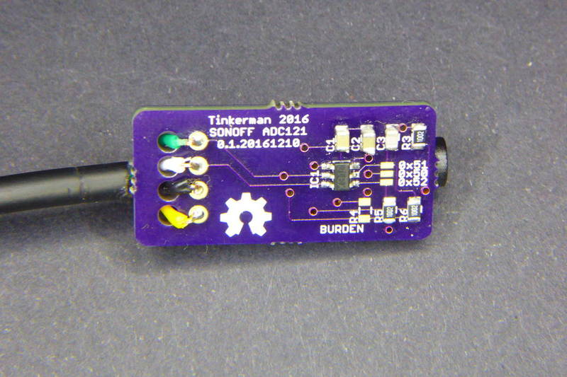
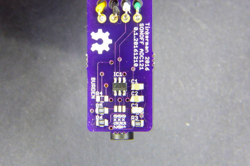
To solder the ADC121 I used solder paste and a hot gun. I'm still newbie using it but I'm improving. Actually, the hardest part was to know the right orientation for the IC. The footprint I had has a dot mark by pin #1, but the SOT6 I received has no dots anywhere, just an X31C label over a line running along the long side.
After investigating a bit I learnt that, usually, if you place the part so you can read the label the pin #1 is in the bottom-left of the IC. Good to know!
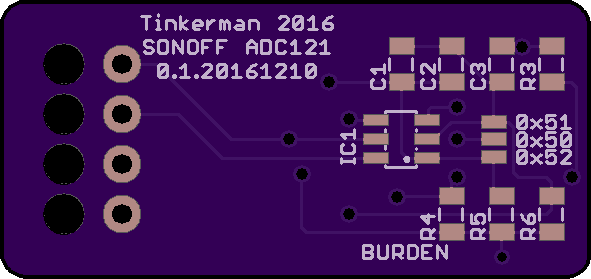
BOM
| ID | Name | Value | Package | Description |
|---|---|---|---|---|
| IC1 | ADC121C027 | SOT-6 | 12bit ADC with I2C interface | |
| - | PJ327A | 3.5mm TRRS socket | ||
| R1 | 10K | SMD0805 | I2C pull-up | |
| R2 | 10K | SMD0805 | I2C pull-up | |
| R3 | 10K | SMD0805 | Filter resistor | |
| R4 | SMD0805 | Burden resistor (value will depend on your CT) | ||
| R5 | 10K | SMD0805 | Bias voltage divider | |
| R6 | 10K | SMD0805 | Bias voltage divider | |
| C1 | 10nF | SMD0805 | ||
| C2 | 4.7uF | SMD0805 | ||
| C3 | 470pF | SMD0805 | Filter capacitor | |
| C4 | 1uF | SMD | Electrolytic |
EmonLiteESP with ADC121 support
The EmonLiteESP library is released as **free open software **and can be checked out at my EmonLiteESP repository on Bitbucket.
Once I had the board I wanted to write some code to test it. There are no ADC121 libraries out there, at least none the I have found. But the functionality I needed was so simple I decided to go straight to the code.
You might know that some time ago a wrote a simple power monitor library for the ESP8266 platform inspired in the EmonLib library for Arduino. The EmonLiteESP library does not implement all the functionality of the original library for Arduino and it's not API compatible. It only monitors current, no voltage, so you can not get active power, only apparent power. But on the other side the reading is not tied to a specific analog GPIO. Instead you have to define a function callback that will return the analog reading using whatever sources you want, in particular using an I2C ADC.
It might sound complicated, but it's not. The simplest function would be that returning the value from an analog pin:
unsigned int currentCallback() {
    return analogRead(CURRENT_PIN);
}
You will then pass this function to the library constructor so it knows how to get the reading. Much more flexible. Because now I want to get the value from an ADC121:
unsigned int currentCallback() {

    unsigned int value;

    // Ask for a reading
    Wire.beginTransmission(ADC121_ADDRESS);
    Wire.write(ADC121_REG_RESULT);
    Wire.endTransmission();

    // Get value (12 bits in 2 bytes)
    Wire.requestFrom(ADC121_ADDRESS, 2);
    if (Wire.available() <= 2) {
        value = (Wire.read() & 0x0F) << 8;
        value |= Wire.read();
    }

    return value;
}
You see, the rest of the code does not change. This pattern is called the strategy pattern in books because it lets you define what strategy the library should use to execute a certain action, like getting an analog value.
Using the Brzo I2C library
The Wire library is part of the Arduino Core for ESP8266 and is API compatible with the Arduino library with the same name. But recently I knew about an implementation of the I2C protocol written in assembly (!!!) specifically for the ESP8266 platform by Pascal Kurtansky. The Brzo I2C library is open source and it's available in the PlatformIO library manager.
What does it mean it's written in assembly? Well, basically it means that it's fast. How fast? A lot faster than the Wire library. In the EmonLiteESP repo you can find two examples for the ADC121, one using the Wire library and a second (adc121_fast) using Pascal's implementation. Running the example using the Wire library with 1000 samples takes 544ms for each reading. The same with the Brzo I2C library takes only 85ms!! That's 6.4 times faster!! Amazing. Actually you have to be sure you get at least one full period of the current wave. For a 50Hz system that's 20ms. So 1000 samples are still 4 full periods.
The problem with the 544ms, aside from the obvious fact that it takes more time, is that 1) you get less samples per period, so your wave representation is very pixelated, so to say, and 2) you can get into problems with your wifi connection or other services that might need more attention.
Let me copy here the full example of the ADC121 using the Brzo I2C library. Some things to notice:
- Same as with the Wire library for ESP8266 you can choose which two GPIOs to use as SDA and SCL. In the Arduino boards (in ATMega328 controllers) these are fixed in hardware.
- The Brzo I2C library always uses buffers to send and receive data.
- You have more fine grain control over the protocol, like SCL frequency and clock stretch time.
- The current callback I talked about before is implemented here as a lambda function, that's the “[]() -> unsigned int { …” stuff. There is no need to do it this way.
/*

EmonLiteESP ADC121 Example using Brzo I2C library

Energy Monitor Library for ESP8266 based on EmonLib
Currently only support current sensing

Copyright (C) 2017 by Xose Pérez <xose dot perez at gmail dot com>

This program is free software: you can redistribute it and/or modify
it under the terms of the GNU General Public License as published by
the Free Software Foundation, either version 3 of the License, or
(at your option) any later version.

This program is distributed in the hope that it will be useful,
but WITHOUT ANY WARRANTY; without even the implied warranty of
MERCHANTABILITY or FITNESS FOR A PARTICULAR PURPOSE.  See the
GNU General Public License for more details.

You should have received a copy of the GNU General Public License
along with this program.  If not, see <http://www.gnu.org/licenses/>.

*/

#include <Arduino.h>
#include "EmonLiteESP.h"
#include "brzo_i2c.h"

// -----------------------------------------------------------------------------
// Configuration
// -----------------------------------------------------------------------------

// I2C CONFIGURATION
#define I2C_SDA_PIN             4
#define I2C_SCL_PIN             14
#define I2C_CLOCK_STRETCH_TIME  200
#define I2C_SCL_FREQUENCY       1000

// ADC121 Address
#define ADC121_ADDRESS          0x50

// ADC121 Registers
#define ADC121_REG_RESULT       0x00
#define ADC121_REG_ALERT        0x01
#define ADC121_REG_CONFIG       0x02
#define ADC121_REG_LIMITL       0x03
#define ADC121_REG_LIMITH       0x04
#define ADC121_REG_HYST         0x05
#define ADC121_REG_CONVL        0x06
#define ADC121_REG_CONVH        0x07

// If you are using a nude ESP8266 board it will be 1.0V
// If using a NodeMCU there is a voltage divider in place, so use 3.3V instead.
#define REFERENCE_VOLTAGE       3.3

// Precision of the ADC measure in bits. Arduinos and ESP8266 use 10bits ADCs.
// The ADC121 is a 12bits ADC
#define ADC_BITS                12

// Number of decimal positions for the current output
#define CURRENT_PRECISION       2

// This is basically the volts per amper ratio of your current measurement sensor.
// If your sensor has a voltage output it will be written in the sensor enclosure,
// something like "30V 1A", otherwise it will depend on the burden resistor you are
// using.
#define CURRENT_RATIO           30

// This version of the library only calculate aparent power, so it asumes a fixes
// mains voltage
#define MAINS_VOLTAGE           230

// Number of samples each time you measure
#define SAMPLES_X_MEASUREMENT   1000

// Time between readings, this is not specific of the library but on this sketch
#define MEASUREMENT_INTERVAL    10000

// -----------------------------------------------------------------------------
// Globals
// -----------------------------------------------------------------------------

EmonLiteESP monitor;

// -----------------------------------------------------------------------------
// Energy Monitor
// -----------------------------------------------------------------------------

void powerMonitorSetup() {

    // Init I2C protocol
    brzo_i2c_setup(I2C_SDA_PIN, I2C_SCL_PIN, I2C_CLOCK_STRETCH_TIME);

    // Set the ADC121 fo manual readings (no automatic sampling)
    uint8_t buffer[2];
    buffer[0] = ADC121_REG_CONFIG;
    buffer[1] = 0x00;
    brzo_i2c_start_transaction(ADC121_ADDRESS, I2C_SCL_FREQUENCY);
    brzo_i2c_write(buffer, 2, false);
    brzo_i2c_end_transaction();

    // Setup power monitor
    monitor.initCurrent([]() -> unsigned int {

        unsigned int value;
        uint8_t buffer[2];

        // Ask for a reading
        brzo_i2c_start_transaction(ADC121_ADDRESS, I2C_SCL_FREQUENCY);
        buffer[0] = ADC121_REG_RESULT;
        brzo_i2c_write(buffer, 1, false);

        // Read the value
        brzo_i2c_read(buffer, 2, false);
        brzo_i2c_end_transaction();
        value = (buffer[0] & 0x0F) << 8; value |= buffer[1]; return value; }, ADC_BITS, REFERENCE_VOLTAGE, CURRENT_RATIO); monitor.setPrecision(CURRENT_PRECISION); } void powerMonitorLoop() { static unsigned long last_check = 0; if ((millis() - last_check) > MEASUREMENT_INTERVAL) {

        unsigned long start = millis();
        double current = monitor.getCurrent(SAMPLES_X_MEASUREMENT);
        Serial.printf("[ENERGY] Sampling time: %ldms\n", millis() - start);
        Serial.printf("[ENERGY] Power now: %dW\n", int(current * MAINS_VOLTAGE));

        last_check = millis();

    }
}

// -----------------------------------------------------------------------------
// Main methods
// -----------------------------------------------------------------------------

void setup() {
    Serial.begin(115200);
    powerMonitorSetup();

}

void loop() {
    powerMonitorLoop();
    delay(1);
}
"Power monitoring with Sonoff TH and ADC121" was first posted on 25 January 2017 by Xose Pérez on tinkerman.cat under Code, Projects and tagged adc121, ads1115, arduino, brzo i2c, current, emonlib, emonliteesp, esp8266, espurna, i2c, itead, itead studio, Pascal Kurtansky, platformio, power, power measurement, power sensor, sonoff, sonoff th, wire.