New firmware for the Slampher
Some weeks ago I received a parcel from Itead. Previously, I had written about the Sonoff and they were kind enough to send me two more of their home automation products for me to review: the S20 Smart Socket I wrote about two weeks ago and the Slampher.
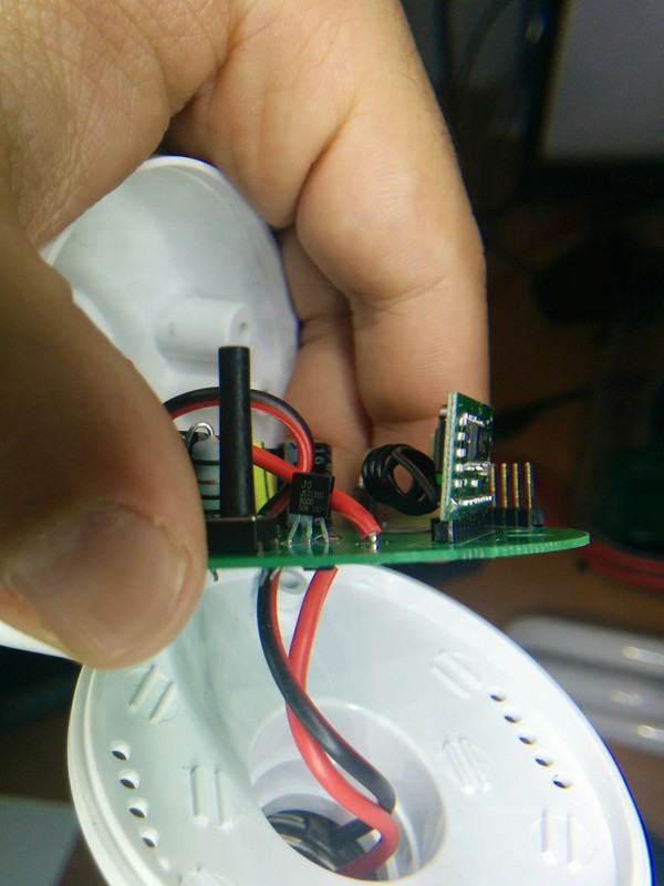
The Slampher is kind of a Sonoff RF that sits before any light bulb with an E27 screw. As you can see in the header pic of this post it adds quite some length to the group. It's a bit bulky and might not fit in every lamp. Off course the board layout is different from the Sonoff and it uses a JST131U-800D 1A triac instead of a relay to switch the bulb. Aside from that they are equivalent.
There are a number of reviews of the Slampher that focus in the basic usage or that go more in depth tearing it apart or flashing custom firmware. As you can guess, I'm more interested in the later. I already exposed my reasons in my post about the S20 Smart Socket and this week it has become more apparent as a report from Bitdefender has uncovered a bug on a commercially available smart socket that would allow attackers to create a malicious botnet. An army of owned sockets!
We are only a few days away from the arrival of the ESP32 and the ESP8266 is still one of the kings of the IoT block, and a really a successful one. Itead choice of using Espressif chips on their home automation line of products make them a hackers dream.
There are a few firmware projects available that will work on the Slampher, including my Espurna Firmware. Most of them have MQTT support and a web configuration portal. Some, like the Espurna, are light enough to support OTA with the 1Mb flash memory that the Sonoff or the Slampher have.
GPIO0 problem
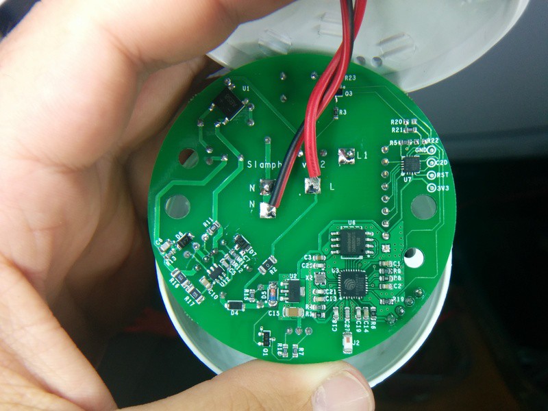
The Slampher and the Sonoff RF both have a 8bit EFM8BB10F2G-A-QFN20 microcontroller (from the EFM8 Busy Bee family) by Silabs that listens to the radio module messages and handles the on-board button. That button is tied to GPIO0 in the Sonoff TH or the S20 Smart Socket and it can be used to enter into flash mode upon boot. Same things does not happen on the Slampher.
The EFM8BB1 intercepts the button events so it can enter into “pairing mode” when the user double-clicks the button. In pairing mode it listens and stores a new radio code that will become the code to toggle on and off the switch from then on. But the curious thing is that if there is a single click event it just pulls down GPIO0 in the ESP8266 like the the button does in the non-RF versions. So Sonoff firmware will work just the same except for:
- You cannot use the button to enter flash mode in the ESP8266 (since it's a user firmware event that pulls GPIO0 down and no user firmware is running at boot time).
- You can't use double click events on your firmware because these are intercepted by the EFM8BB1, unless they are more than about half a second away from each other.
- You can't use long click events since the EFM8BB1 pulls GPIO0 down only on button release for about 125ms.
Issues #2 and #3 you will have to live with them. My Espurna firmware uses double click and long click events to enter AP mode and to reset the board respectively. That will not work on the Slampher. I could extend the double click interval in the DebounceEvent library from 500ms to 1000ms, but it won't be very user friendly.
Issue #1 has different solutions. Scargill suggests to move resistor R21 to R20, so the button is now attached to ESP8266 GPIO0 (check the schematic at Itead wiki). Problem is that you lose the ability to pair your remote. Off course you could pair it first and then move the resistor but chances are that in the long run you will need to pair it more often than flash it, because you have OTA.
Flashing the Slampher
So my solution is to momentarily shortcut to ground the unpopulated pad of R20 that goes to GPIO0 and power the device at the same time. It's not easy, you will need some practice and you will probably have to do it more than once. But at the end you will have a customized Slampher with fully working RF support.
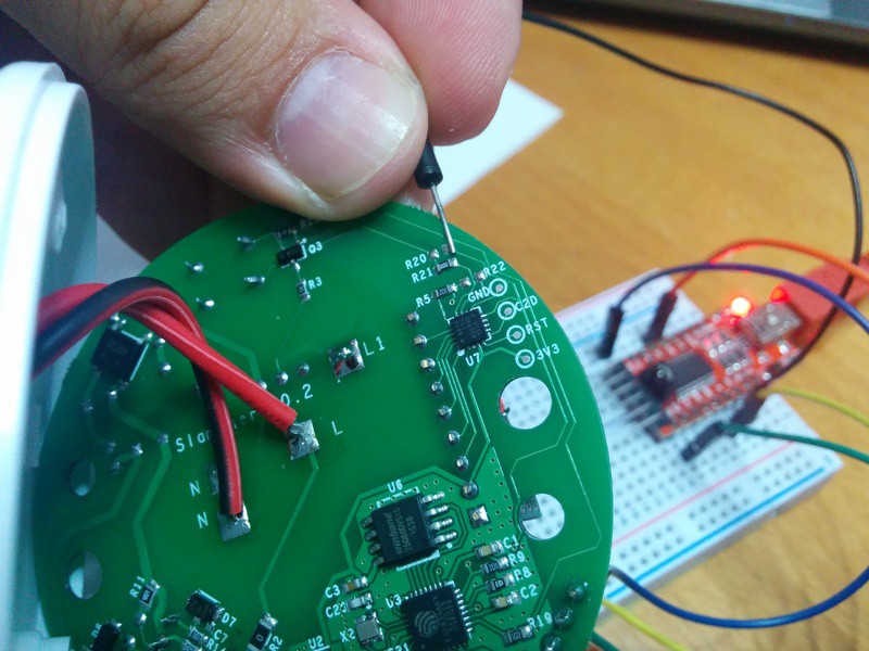
Off course I'm assuming you have a stable OTA-able firmware and that you have a testing platform (I have a Sonoff just for that). Also, you can add a new button between the pad and GND to flash the device in a more comfortable way.
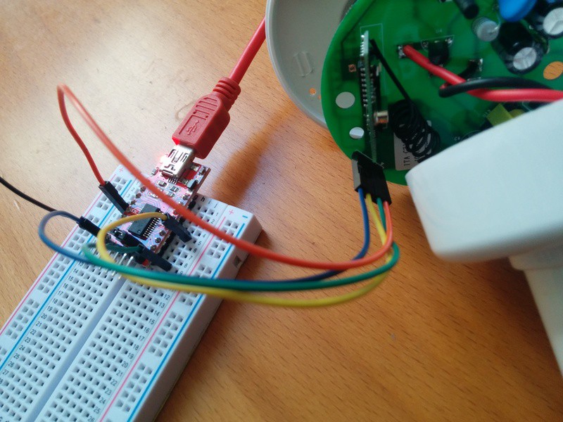
The Slampher has a 4 pins header that brings out everything you need to flash it (except for GPIO0), counting from the little white mark onwards: VCC, RX, TX and GND. You just need to wire your favourite USB to UART board (an FTDI-like) and you are ready to go. Just remember: the ESP8266 requires 3V3, not 5V! And connect TX to your programmer RX and RX to TX. Then you will need to handle the board with care with another ground jumper wire touching the R20 right pad (check the images) while you disconnect and connect you FTDI board or the VCC cable.
Radio control
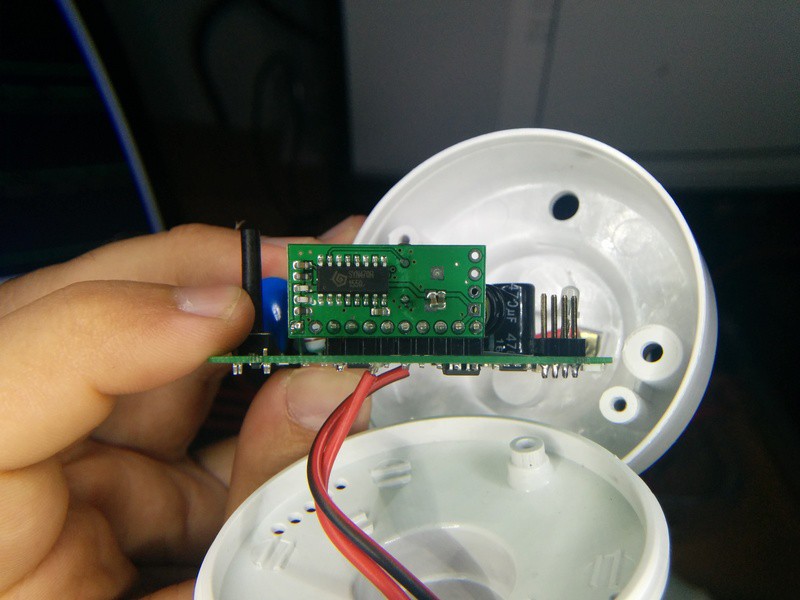
The radio receiver chip is a SYN470R by Synoxo in a 16 pin SOP package. This is a ASK/OOK RF transparent link (an “antenna-in to data-out” as the manufacturer says). It needs a microncontroller to act as a logic decoder. You can configure the bandwidth and it has a WAKEUP pin you can use to wake up your controller when there is a radio signal.
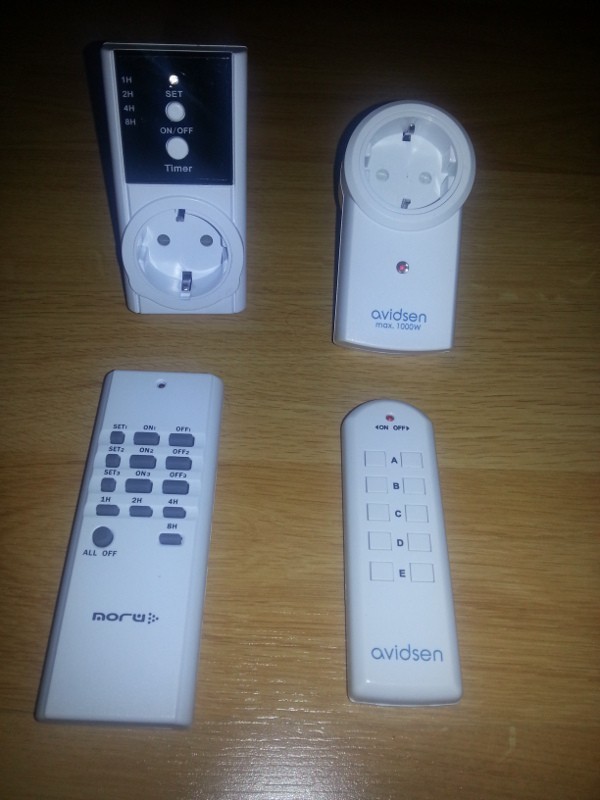
First I tried to pair it with my Avidsen remote without success. Then I used another remote I have for Noru radio sockets and it worked! Kind of… The red LED in the radio modules blinked while pairing it but not all the buttons worked. Only ON1, OFF2, OFF3 and 8H buttons on my Noru remote actually work with the Slampher. Weird.
Decoding the radio signals
So I reviewed my own post about decoding radio signals but instead of using my Bus Pirate I give it a try to the RCSwitch library first, using the basic receiver example and adding some code to output “normalized” data strings, I started decoding the 4 buttons of the remote Itead is selling. This is the code I used:
#include <RCSwitch.h>;

RCSwitch mySwitch = RCSwitch();

void setup() {
  Serial.begin(115200);
  mySwitch.enableReceive(0);  // Receiver on inerrupt 0 =>; that is pin #2
}

void loop() {
  if (mySwitch.available()) {

    int value = mySwitch.getReceivedValue();

    if (value == 0) {

      Serial.print("Unknown encoding");

    } else {

      Serial.print("Received ");
      Serial.print( mySwitch.getReceivedValue() );
      Serial.print(" / ");
      Serial.print( mySwitch.getReceivedBitlength() );
      Serial.print("bit ");
      Serial.print("Protocol: ");
      Serial.print( mySwitch.getReceivedProtocol() );

      char binary[25] = {0};
      char tristate[13] = {0};
      int count = 0;
      int tri = 0;

      unsigned int * timings = mySwitch.getReceivedRawdata();
      for (int i=1; i<49; i=i+2) {           binary[count++] = (timings[i] > 500) ? '1':'0';
          if (count % 2 == 0) {
              if (binary[count-2] == '0') {
                 tristate[tri++] = (binary[count-1] == '0') ? '0' : 'F';
              } else {
                 tristate[tri++] = (binary[count-1] == '0') ? 'X' : '1';
              }
          }
      }

      Serial.print(" Binary: );
      Serial.print(binary);
      Serial.print(" Tristate: );
      Serial.println(tristate);

    }

    mySwitch.resetAvailable();

  }

}
The output of the 4 buttons from the Itead remote is:
| Button | Value | Binary | Tetrabits |
|---|---|---|---|
| A | 11708433 | 101100101010100000010001 | X10XXXX00F0F |
| B | 11708434 | 101100101010100000010010 | X10XXXX00F0X |
| C | 11708436 | 101100101010100000010100 | X10XXXX00FF0 |
| D | 11708440 | 101100101010100000011000 | X10XXXX00FX0 |
As you can see they are 24 bit messages where the first 20 are the same for the 4 buttons and then there is only one bit set for the remaining 4 bits. The 4 buttons in the Noru remote that work have only 1 bit set in the last 4. That's why the remote Itead sells has only 4 buttons. I still don't know if I can use Itead's remote with the Noru sockets since I never managed to know the relation between button codes (between ON and OFF buttons that control the same socket). But they don't look compatible…
Note: one funny thing is that there is another EFM8BB1 microcontroller on the radio module. What? Maybe the radio decoding is done in this second chip while the one in the Slampher board is just responsible for the button and the GPIO0?
Wrapping up
The Slampher might be a bit bulky and it won't fit in all the lamps (it does protrude from the livingroom lamp cover at home) but it's a fine device for home automation. My criticism to the eWeLink app and my concerns about really owning the device still stand. But I will no doubt tell you: go buy one, flash it with your own firmware and enjoy.
"New firmware for the Slampher" was first posted on 23 August 2016 by Xose Pérez on tinkerman.cat under Analysis, Code, Projects and tagged avidsen, bitdefender, bus pirate, efm8bb1, esp32, esp8266, espressif, espurna, ewelink, itead, mqtt, noru, ota, radio decoding, rcswitch, s20 smart socket, silabs, slampher, sonoff, syn470r, synoxo.