Moteino Energy Monitor Shield
Moving from the ESP8266 world I've been diving lately I still love the simplicity of battery powered Moteino nodes. You might know I'm migrating my XBee-based sensor network at home to an RFM69 one. So long I have changed my door monitor and my weather station. They are sensing and reporting to my RFM69GW, an ESP8266 bridge board using a custom firmware.
Time to go for the power monitor. A long time ago (actually 2 years but it really feels like a century ago) I was living in a big city and we had one of those fancy “smart meters” with a LED pulsing 4000 times every kWh. Back then I used an Arduino micro to count the LED pulses and report the power every minute through an XBee link.
But now I live in a small town and my house electrical system is somewhat “old”. My power meter comes from somewhen in the 60s (maybe not so old). So a non-invasive current sensor makes a bit more sense (ehem).
Power monitoring
Monitoring my home power consumption is not the only reason I have to work in this project. I will talk about the other motivations I have soon (I hope). For now let me list here the requirements:
- Long-life battery powered node
- Compatible with different radios
- Compatible with different non-invasive current sensors out there
- Modular, from 1 to 3 monitoring lines
- Cheap to produce
I did not want to spend a lot of money on the boards so making them small made sense. I also wanted the component count to be low. I don't need super-exact readings, so I discarded adding a buffered input or an opamp amplifier.
Using Moteino as the platform is also a good choice. The board is small and with just the proper components. It supports different radios already and it's meant to be stackable. And the awesome work of Felix Rusu and Thomas Studwell with the RFM69 library with automatic power transmit control and RocketScream Low-Power library can make it really low-power.
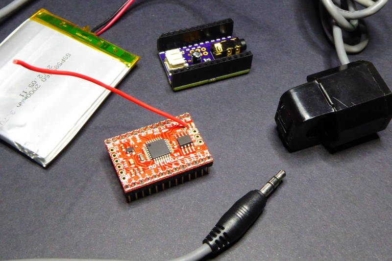
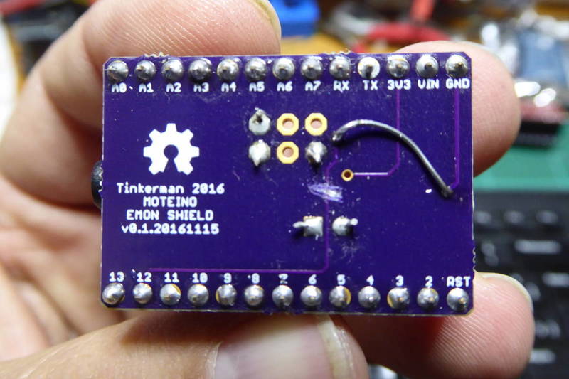
Moteino Energy Monitor Shield
The Moteino Energy Monitor Shield schematics, board layout and firmware are released as **free open hardware & software **and can be checked out at my **eMoteino repository **on Bitbucket. Also, you can order the Moteino Energy Monitor Shield v0.2 board from OSHPark.
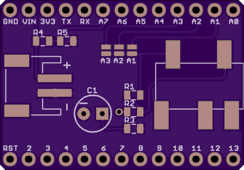
So, this is the energy monitor shield for Moteino. Version 0.2 has:
- a Moteino shield form factor
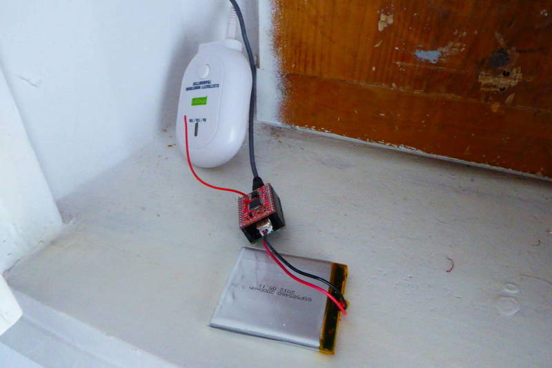
- a PJ-327A 3.5mm stereo jack to connect the CT
- an S2B-PH-SM4-TB LiPo connector
- one optional 0805 burden resistor (R1)
- two 0805 470K resistors and a 10uF electrolytic capacitor for the voltage bias
- two 0805 470K resistors for the battery monitor
- three SMD solderpads to choose the analog GPIO to use
Shield options
From the hardware point of view you have different options. First, depending on the current clamp you are using, you might need to use an external burden resistor. Basically you need to know whether your sensor outputs a “voltage” or a “current”. If the former you will probably read something like “30A/1V” somewhere in the sensor body or in the datasheet. If the later it will read something like “30A/15mA”.
If you have a current you will need to convert it to a voltage so the ATMega328 in the Moteino can read it. The way to do it is adding a burden resistor across the clamp outputs. Head over to the Open Energy Monitor project for more info about how to calculate the burden resistor. In my case I'm using an EChun ECS1030-L72 with a 1:2000 turn ratio, so I used a 68Ohm resistor so I can read roughly 30A per volt output. (30A * 68Ohm / 2000 = 1.02V). The max output voltage (1V in my case) times 1.41 (the square root of 2) has to be less than half the reference voltage.
Second you have to** choose the analog GPIO** you will use to read the current sensor output. You can choose between A1, A2 or A3 by adding solder over the appropriate solder jumper. If you are stacking more than one shield make sure you use different analog GPIOs for each one.
Third choice is to enable battery monitoring. If you don't need it, just don't add the lipo connector or the battery monitoring voltage divider (R4 and R5). Also if you stack more than one shield, you just need to add those to one of them.
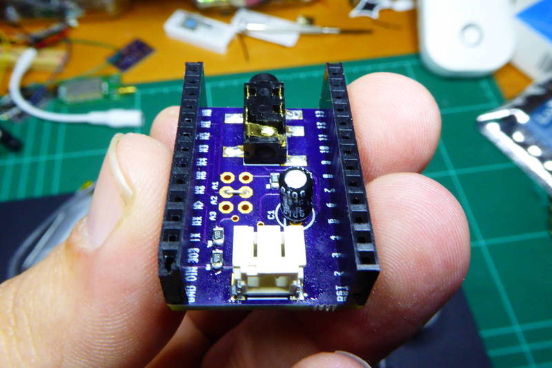
Version 0.1 problems
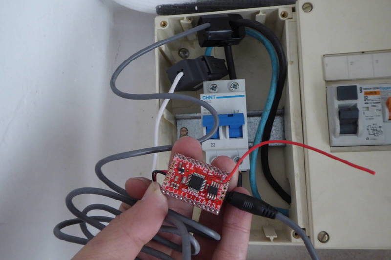
You might have noticed that I've been talking about v0.2. Pictures in this post are from v0.1, like the one bellow. My first design included a battery monitor with the downstream resistor connected to GPIO12 instead of ground. The idea, suggested by user “john k2ox” in the LowPowerLabs forum, was to save some energy by setting the pin in high impedance mode while not reading the voltage.
I don't know why it does not work but when you set the pin to OUTPUT LOW the analog GPIO keeps on reading the VCC voltage instead of half the battery voltage… As a quick fix I cut the trace to GPIO12 and solder a wire to ground instead. After all we are talking about 3.3V / 940k ~ 3.5uA.
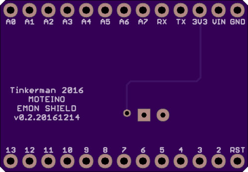
Also you might have notice the solderpads in v0.2 were simple jumpers in v0.1. Truth is that the 2x3 header I wanted to solder there barely fit under the Moteino.
Firmware
The Moteino Energy Monitor Shield schematics, board layout and firmware are released as **free open hardware & software **and can be checked out at my **eMoteino repository **on Bitbucket.
The code is very similar to the one in the other Moteino based nodes I have deployed so far. The main difference is that I perform a reading every time the board wakes, that's every 4 seconds, and then average all the readings every minute before transmitting them. The actual number of readings in a minute has to be hand tuned to because other stuff the controller does while awake (in particular the sampling) takes some time. I found out that 13 4-seconds sleep cycles make one minute ;)
void loop() {

    // Reset the accumulator before entering the loop
    sum = 0;
    count = 0;

    // Sleep loop
    // 15 times 4 seconds equals 1 minute,
    // but in real life messages are received every 77 seconds
    // with this set up, so I'm using 13 here instead...
    for (byte i = 0; i < SLEEP_CYCLE; i++) {

        // Sleep for 4 seconds (the maximum the WDT accepts)
        LowPower.powerDown(SLEEP_FOR, ADC_OFF, BOD_OFF);

        // At this point we perform a reading
        double current = getCurrent(CURRENT_SAMPLES);
        sum += current;
        ++count;

        // Debug
        //Serial.print("[MAIN] Current: ");
        //Serial.println(current);
        //delay(50);

    }

    // Send the readings
    send();

}
You can configure almost everything from the settings.h file (you will first have to make a copy from the settings.h.sample). In particular pay attention to the CURRENT_RATIO constant. I use to compare values with other power meters I have at home (an Efergy, a no-name chinese one and a current clamp) and I modify this value to match the other's readings.
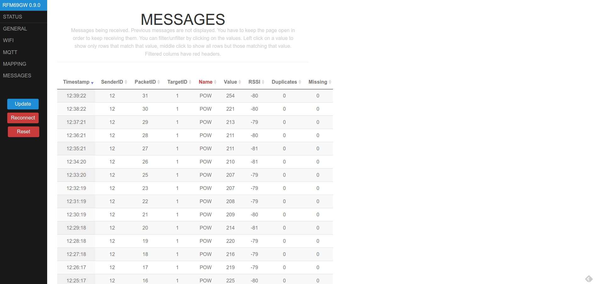
Currently the firmware only supports one line. Will be adding support for up to 3 readings soon. In the meantime my RFM69GW gateway is receiving packets from my Moteino energy monitor.
"Moteino Energy Monitor Shield" was first posted on 14 December 2016 by Xose Pérez on tinkerman.cat under Projects and tagged burden resistor, current, current clamp, current transformer, energy monitor, lowpowerlabs, moteino, open energy monitor, oshpark, rfm69, rfm69gw, shield, xbee.