Low power in LoRaWan world - Meet the RN2483
I'm working on a project were I have to build a network of battery powered sensors over a territory the size of a small town.The sensors will monitor power consumption, temperature and humidity in energy poor households. Often the families in that situation can't afford an internet connection at home so WiFi is out of question. GPRS would be an option but lately other radio technologies have come to my interest.
I'm a core member of The Things Network Community in Catalunya. LoRa is one such technologies. The (soon) availability of affordable gateways and the open nature of the software stack (from gateway firmware to backends to handlers) make it a great candidate to build an open, libre wireless sensor network that can cover large territories with few gateways.
Someday soon I'll talk about the gateways, backends and so. Now I'm focusing on nodes. The idea is very similar to my previous post about a Moteino energy monitor node with an RFM69 radio, but using a LoRa radio and LoRaWan protocol instead. There are several options here. The cheaper and more common is to use a HopeRF RFM9X LoRa module and implement the LoRaWan specification in code. There are already libraries for arduino and alike that implement the LoraMAC specification almost at 100%. But for my first try I used another approach.
Microchip is selling a serial module that implements the full LoRaWan stack and communicates with your favourite uC through serial. The Microchip RN2483 (in the EU) is very easy to use and it's price is not very different from HopeRF modules (both are about 15 euros at DigiKey). It's the same module that the people at The Things Network have used for their The Things Uno prototyping platform (and Arduino Uno with a RN2483 module).
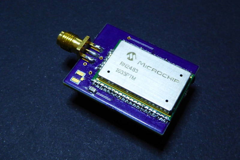
Question is: is the RN2483 a good choice for a battery powered LoRaWan node?
Yet another Moteino shield
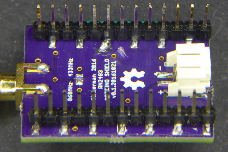
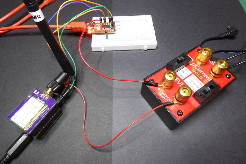
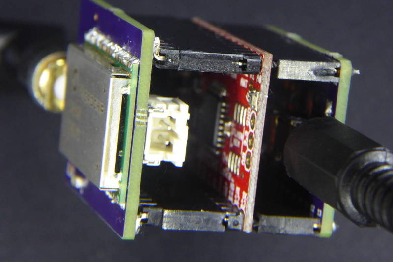
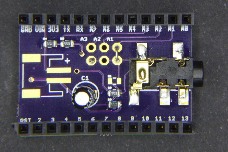
Right. Since I'll be using a Moteino as the development platform I thought it would be nice to have shield for the RN2483. Problem was that the module is too wide to fit between the two rows of pins… so I decided to use SMD headers on the bottom and leave some space to solder the module without problems. The shield is slightly bigger than the Moteino, it has a footprint for a decoupling capacitor and connectors for a SMA or a uFL antennae that you can connect either to the 433 or the 868 RF pins.
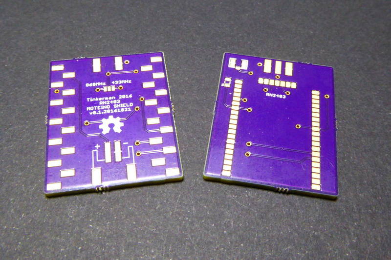
I also added an S2B-PH-SM4-TB LiPo connector for convenience**.**
Soon I found out that v0.1 had an almost-fatal mistake on the digital row of pins. It's flipped! so the RX and TX pins of the RN2483 are not connected to D3 and D4 as I originally designed but to D11 and D10. That's not much of a problem, but it was that the RST pin was connected to D9 instead of D5. Why is that a problem? D9 is connected to the on-board LED on the Moteino. I'll be honest: I lost maybe an hour debugging a problem in my code because the board was resetting when sending a message. Got it? I was blinking the LED to notify the message sending… My solution was to cut the RST trace and solder it to a pin closer to one of the vias, which happened to be D6. So now I can light the LED without side-effects :)
Libraries out there
There are at least 4 open source libraries out there to manage the RN2483 from the arduino framework.
- SmartEverything Lion RN2483 by Amel Technology
- Sodaq RN2483 by Sodaq
- RN2483 Library by JP Meijers
- The Things Network Arduino Library by TTN
The Sodaq library is the one I like the most but for this test I have used the TTN library even thou it lacked one of the key features for the project: sleep. Anyway implementing it is really simple (even thou the library insides are unnecessarily complex). The sleep command is a simple:
sys sleep 5000
for a 5000 milliseconds sleep. But the library implementation is quite verbose:
void TheThingsNetwork::sleep(unsigned long msec) {
    if (100 < msec && msec < 4294967296) { while (modemStream->available()) {
          modemStream->read();
        }
        debugPrint(F(SENDING));
        sendCommand(SYS_TABLE, SYS_PREFIX, true);
        sendCommand(SYS_TABLE, SYS_SLEEP, true);
        char buffer[11];
        sprintf(buffer, "%ld", msec);
        modemStream->write(buffer);
        debugPrint(buffer);
        modemStream->write(SEND_MSG);
        debugPrintLn();
    }
}
I forked the library, added the code to my version and issued a pull request. In the meantime let's go forward with the numbers…
Make the radio awake the uC
During my firsts test I soon realised it was hard and really poorly efficient to asynchronously sleep the radio and the microcontroller. My goal was to sleep the radio for 5 minutes (for instance) and then cycle sleep the ATMega328 in the Moteino during 8 seconds every time, read the power consumption with the non-invasive current sensor (using the same shield here as in my previous post). The problem is that the sleeping intervals for the WDT (using the LowPower library by ScreamRocket) are discreet, thick grained, and it does not let you take into account the time you spend awaken. So at the end 15 cycles of 4 seconds are more like 72 seconds…
You can do less cycles, of course, but then you have two possible problems:
- You are ready to send but the radio is still sleeping, or
- when you are finaly ready to send the radio has been awaken for seconds waiting for you and drying your batteries.
But you might have noticed in the previous section that the radio sleep command takes an argument in milliseconds… Wow. Interesting. What if I could sleep the radio for, say, 9560ms and make it awake the microcontroller afterwards…
Well the datasheet does not mention any trigger pin, sleep pin, hello-I'm-here pin for the RN2483. But after some testing I noticed that the radio outputs a nice “ok” after the sleeping time has passed. So why not? I attached the TX pin on the module to an interrupt pin in my Moteino and, after some testing, I had it working!! Cool.
Let me show you something:
void sleepRadio() {
    #ifdef DEBUG
        Serial.println("[MAIN] Sleeping the radio");
    #endif
    ttn.sleep(SLEEP_INTERVAL - millis() + wakeTime);
    if (loraSerial.available()) loraSerial.read();
}

void sleepController() {
    #ifdef DEBUG
        Serial.println("[MAIN] Sleeping the controller");
        Serial.println();
        delay(10);
    #endif
    attachInterrupt(1, awake, CHANGE);
    LowPower.powerDown(SLEEP_FOREVER, ADC_OFF, BOD_OFF);
    wakeTime = millis();
    detachInterrupt(1);
    if (loraSerial.available()) loraSerial.read();
    #ifdef DEBUG
        Serial.println("[MAIN] Awake!");
    #endif
}
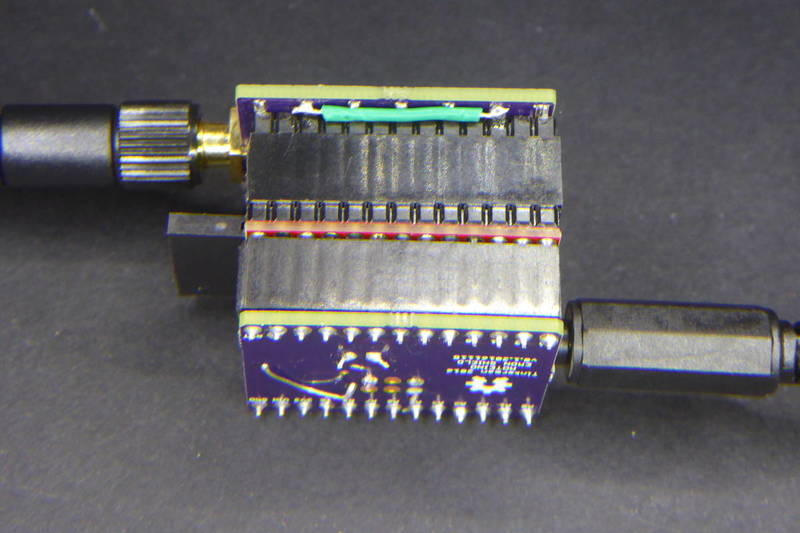
These two methods take care of the radio and the microcontroller sleeping. Notice the microcontroller is set to sleep forever and only an interrupt on D3 (interrupt pin 1) will awake it. I soldered a cable from the D11 (radio TX pin) to D3. The wakeTime variable is a global variable that holds the millis() when the microcontroller last woke up. When I set the radio to sleep again I correct the sleeping time to take into consideration the amount of time it has been awake so far. That results in a pretty precise sinchronisation.
Some numbers
The Moteino I'm used lacks a radio module or an SPI Flash memory like most have. So power consumption depends on the regulator, the LED and, of course, the controller. Under normal use the Moteino alone uses about 7-8mA. The RN2483 add 3mA to that when not transmitting. So in total we have something in the 11mA with the LED off and no radio transmission.
Sleeping the radio removes most of those 3mA but we need to sleep the controller too to see how long will we be able to power the node with a normal LiPo battery. The simple rough test a did was:
ttn.sleep(3600);
LowPower.powerDown(SLEEP_FOREVER, ADC_OFF, BOD_OFF);
And the result was under 40uA. Not bad! We are certainly in the Low Power Kingdom. With that values we could (theoretically) power the node with a 1000mAh LiPo battery for almost 3 years. But we should also take into account non-sleeping times.
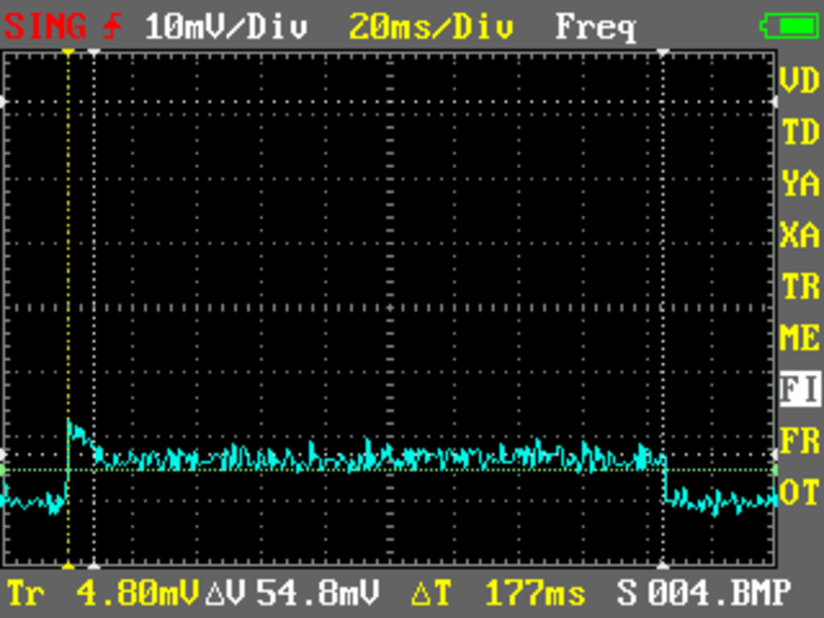
This first graph shows a “normal” cycle, no sending, just reading values from the ADC. The time windows is pretty big, around 177ms. This is because the way we are monitoring current, sampling up to 1000 different readings to calculate the root mean square of all of them. Mind it's AC current we are monitoring. The average current is 7-8mA as expected.
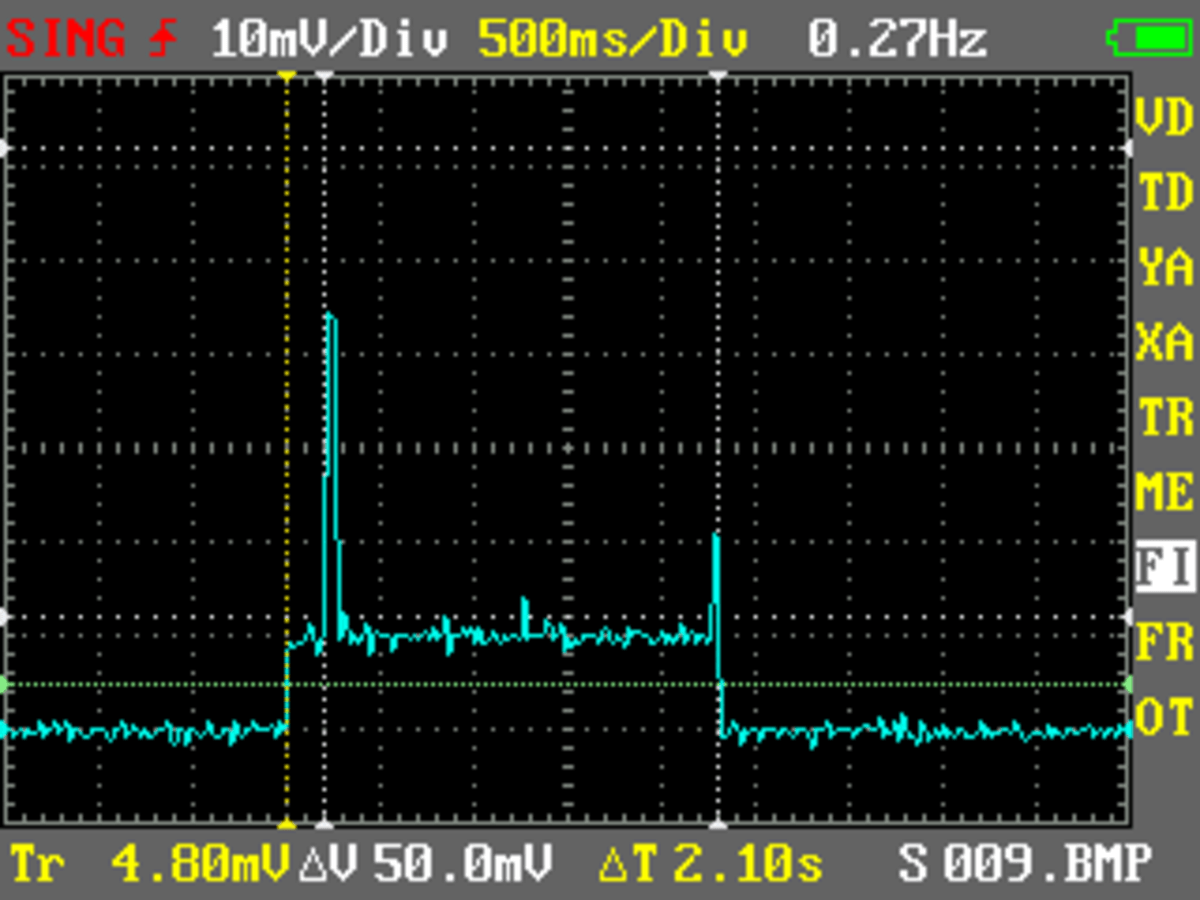
This second graph shows the radio sending and waiting for the RX windows. The time window is 2.1 seconds!! Actually this is the debug output of the node:
Sending: mac tx uncnf 1 002500000000000000001360
Airtime added: 1.84 s
Total Airtime: 1.84 s
Successful transmission
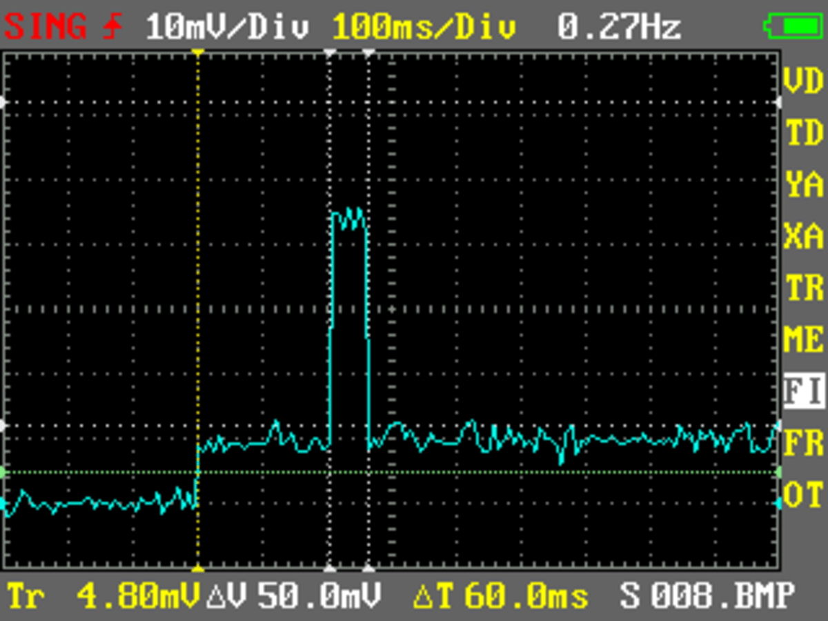
It takes 1.84 seconds to send 12 bytes! Sure there are diferent data rates you can use. For the tests the node was set to “adaptative data rate". That means the gateway tells the node what data rate to use in next transmission based on noise, distance, traffic,… During those 2.1 seconds consumption is slightly over 10mA with two peaks. The first one goes up to 40-something mA during 60 miliseconds.
How much does this add up to?
| Stage | mA | ms/event | events/5minutes | mA*ms/5minute |
|---|---|---|---|---|
| Reading sensors | 8 | 180 | 25 | 36000 |
| Radio awaken | 11 | 2100 | 1 | 23100 |
| Sending burst | 50 | 60 | 1 | 3000 |
| Rest of the time | 0.04 | 293340 | 1 | 11734 |
That's about an average of 250uA, which means around 5 months on a 1000mAh battery… Real values are usually 2 o 3 times smaller, so using a 3000mAh battery might be a good idea to have about half a year of autonomy.
Code
The Moteino RN2483 Shield v0.3 schematics, board layout and firmware are released as **free open hardware & software **and can be checked out at my **eMoteino repository **on Bitbucket.
Code for this project is not hard to read, but it's not yet well documented since it's a work in process. Any doubt or question please don't hesitate in asking. Just a couple of this here to clarify:
void loop() {

    // Update counters
    if (++count1 == READING_COUNTS) ++count2;

    // We are only sending if both counters have overflown
    // so to save power we shutoff the radio now if no need to send
    if (count2 < SENDING_COUNTS) sleepRadio();

    // Visual notification
    blink(1, 5);

    // Always perform a new reading
    doRead();

    // We are storing it if count1 has overflown
    if (count1 == READING_COUNTS) doStore();

    // We are only sending if both counters have overflow
    if (count2 == SENDING_COUNTS) {
        blink(3, 5);
        doSend();
        sleepRadio();
    }

    // Overflow counters
    count1 %= READING_COUNTS;
    count2 %= SENDING_COUNTS;

    // Sleep the controller, the radio will wake it up
    sleepController();

}
The main loop of the firmware performs different actions depending on the overflow conditions of two counters. First the radio (and hence the whole system) is set to sleep for 10 seconds. After each sleeping period a current reading is performed. Every 6 readings, i.e. every minute, the average of those 6 values is stored in a vector as a apparent power (current times nominal voltage). And every 5 minutes that vector is sent to the gateway. The code tries to sleep the radio as soon as possible.
void doSend() {

    byte payload[SENDING_COUNTS * 2 + 2];

    for (int i=0; i<SENDING_COUNTS; i++) { payload[i*2] = (power[i] >> 8) & 0xFF;
        payload[i*2+1] = power[i] & 0xFF;
    }

    unsigned int voltage = getBattery();
    payload[SENDING_COUNTS * 2] = (voltage >> 8) & 0xFF;
    payload[SENDING_COUNTS * 2 + 1] = voltage & 0xFF;

    #ifdef DEBUG
        Serial.println("[MAIN] Sending");
    #endif
    ttn.sendBytes(payload, SENDING_COUNTS * 2 + 2, 1, false);

}
The doSend method packs the vector with the power values in 10 bytes and adds two bytes more with the information about the sensor battery reading. This format has to be decoded in the application or in the handler at TTN. The The Things Network backend lets you define payload function for decoding messages which is a good idea for testing but maybe not so much when in production. Anyway the function that would decode the previous format looks like this:
function (bytes) {
  var result = { 'power': [], 'battery': 0 };
  var count = bytes.length / 2 - 1;
  for (var i = 0; i < count; i++) {
    result.power.push(256 * parseInt(bytes[i*2]) + parseInt(bytes[i*2+1]));
  }
  result.battery = 256 * parseInt(bytes[count*2]) + parseInt(bytes[count*2+1])
  return result;
}
Again, this is a work in progress… comments are very welcome!!
"Low power in LoRaWan world - Meet the RN2483" was first posted on 17 December 2016 by Xose Pérez on tinkerman.cat under Code, Projects and tagged energy, hoperf, lora, lorawan, low power, microchip, moteino, rfm95, rfm9X, rn2483, shield, sleep, the things network, the things uno, ttn, ttncat.