The HLW8012 IC in the new Sonoff POW
The HLW8012 is single phase energy monitor chip by the chinese manufacturer HLW Technology. It features** RMS current**, **RMS voltage** sampling and **RMS active power** with an internal clock and a PWM interface in a SOP-8 package. You can buy it at Aliexpress for less than a euro a piece and the necessary components are fairly easy to source and quite cheap.
All in all it looks like a great IC to include power monitoring in your projects. I guess that is why Itead Studio chose it for the Sonoff POW, one of their newest home automation products. And of course I have a POW here in my desk and I've been playing with it this weekend. The goal is to support it in my Espurna firmware but first I wanted to know more about the HLW8012. I'll write about the Sonoff POW in a different post later this week.
HWL8012 basics
The HWL8012 is a 5V IC that monitors both voltage and current and output RMS voltage, current and active power encoded as a 50% duty cycle square wave where the frequency is proportional to the magnitude.
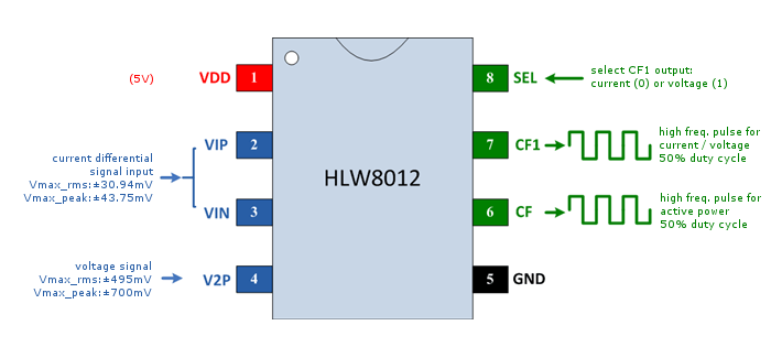
Inputs
Current is measured by a differential potential measure across a milli-ohm copper-manganese resistor in series with the main current flow. The differential potential is fed into pins VIP and VIN. The resistor must be such than the wave in VIP-VIN peaks at 43.75mV maximum. A 1milliohm resistor is well suited to measure currents up to ~30A with a dissipation of less than 1W.
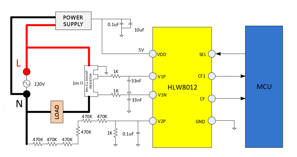
Voltage is measured in the same way but since the V2P pin supports up to 495mV RMS signals the potential has to be scaled down. The HLW8012 datasheet recommends a voltage divider of 6 470kOhm resitors upstream and a 1kOhm resistor downstream. That means a scale factor of 2821 that will convert a 230V RMS into 82mV that falls waaaay below the limit.
The product datasheet suggests the circuit below as a typical application and it's the very same schematic you will find on the Sonoff POW (check it's wiki page for a schematic). Except for the fact that the voltage divider in the Sonoff POW has only 5 470kOhm resistors.
Outputs
On the MCU side of the IC we have two pins that output the square wave. The CF pin pulse frequency increases as the active power increases too. The relation depends on the reference voltage (2.43V), the internal clock frequency (3579kHz typically), the voltage divider in the V2P input and the milliohm resistor. For the suggested application in the datasheet a frequency of 1Hz corresponds to a ~12W active power, 10Hz to ~120W, 100Hz to ~1.2kW and so on.
The CF1 pulse is proportional to the RMS current or voltage, depending on the value in the SEL pin. If SEL is pulled high then the CF1 pin outputs a square wave with a frequency proportional to the RMS current measured. If SEL is pulled down it will ouput the RMS voltage instead. Nominal values (as per datasheet) are 15mA or 0.5V for a 1Hz wave.
A library for the HLW8012
The HLW8012 library for Arduino and ESP8266 is released as **free open software **and can be checked out at my HLW8012 repository on Bitbucket.
The library is still a work in progress as I still have to integrate it in a real project like adding support for the Sonoff POW to my Espurna firmware. So far I have tested stand-alone. The library (as of now) has two ways to monitor pulses: using Arduino “pulseIn” method or using interrupts.
The interrupt-driven approach is the recommended approach but requires you to wire the interrupts to the library. This is so because I didn't want to do that from the library since that would mean creating a singleton instance of the library to be able to route the interrupts (at least, that's the only way I know).
The bare minimum example would be:
(... definitions ...)

HLW8012 hlw8012;

void hlw8012_cf1_interrupt() {
    hlw8012.cf1_interrupt();
}

void hlw8012_cf_interrupt() {
    hlw8012.cf_interrupt();
}

void setup() {

    hlw8012.begin(CF_PIN, CF1_PIN, SEL_PIN, CURRENT_MODE, true);
    attachInterrupt(CF1_PIN, hlw8012_cf1_interrupt, CHANGE);
    attachInterrupt(CF_PIN, hlw8012_cf_interrupt, CHANGE);

    ( ... other setup code ...)

}

void loop() {

    static unsigned long last = millis();

    // This UPDATE_TIME should be at least twice the interrupt timeout (2 second by default)
    if ((millis() - last) > UPDATE_TIME) {

        last = millis();
        Serial.print("[HLW] Active Power (W)    : "); Serial.println(hlw8012.getActivePower());
        Serial.print("[HLW] Voltage (V)         : "); Serial.println(hlw8012.getVoltage());
        Serial.print("[HLW] Current (A)         : "); Serial.println(hlw8012.getCurrent());
        Serial.print("[HLW] Apparent Power (VA) : "); Serial.println(hlw8012.getApparentPower());
        Serial.print("[HLW] Power Factor (%)    : "); Serial.println((int) (100 * hlw8012.getPowerFactor()));
        Serial.println();

    }

    ( ... other loop code ... )

}
Please check the examples folder for more examples on how to use it all together, or use the non-interrupt approach.
Sensor calibration
Internally the library has 3 calibration factors that will apply to the pulse width reading. The actual magnitude (current, voltage or active power) is measured by dividing these values by the pulse width in microseconds.
The formulae are defined in the HLW8012 datasheet and, like I said, depend amongst other factors on the series resistor with the main line and the resistors that create the voltage divider in the V2P input. The library uses the recommended values for the typical application (also in the datasheet) but chances are your device uses a slightly different values of those, like using a 0.002 Ohm resistor instead of the 0.001 Ohm one. Besides, the real values and the nominal ones might not be 100% accurate.
The library provides two calibration methods to improve accuracy. The first calibration methods lets you specify the real values for the resistors around the HLW8012:
...
    hlw8012.begin(CF_PIN, CF1_PIN, SEL_PIN, CURRENT_MODE, true);
    hlw8012.setResistors(CURRENT_RESISTOR, VOLTAGE_RESISTOR_UPSTREAM, VOLTAGE_RESISTOR_DOWNSTREAM);
...
The second calibration method goes a step further and modifies the calibration values so the output matches the expected values for power, current or voltage. Of course if you use this second method the first one is not necessary. To calibrate the sensor using this method you will need some kind of interface to provide the expected values or start the device with a well know load.
The calibration load should be a pure resistive one or you can use an already calibrated commercially available wattimeter to read the values.
...
    // Calibrate using a 60W bulb (pure resistive) on a 230V line
    hlw8012.expectedActivePower(60.0);
    hlw8012.expectedVoltage(230.0);
    hlw8012.expectedCurrent(60.0 / 230.0);
...
The library does not remember the calibration values across reboots so you will have to implement some kind of persistence of your own. You can use the getMultiplier() and setMultiplier() methods to retrieve a manually set these values.
How does it work?
In the interrupt-driven approach, the library monitors the pulses in the background. When the code calls the getActivePower, getCurrent or getVoltage methods the last sampled value is returned. This value might be up to a few seconds old if they are very low values (a 6W LED lamp will output a ~0.5Hz square wave). This is specially obvious when switching off the load. The new value of 0W or 0mA is ideally represented by infinite-length pulses. That means that the interrupt is not triggered, the value does not get updated and it will only timeout after 2 seconds (configurable through the pulse_timeout parameter in the begin() method). During that time lapse the library will still return the last non-zero value.
On the other hand, when not using interrupts, you have to let some time for the pulses in CF1 to stabilise before reading the value. So after calling setMode or toggleMode leave 2 seconds minimum before calling the get methods. The get method for the mode currently active will measure the pulse width and return the corresponding value, the other one will return the cached value (or 0 if none).
Use non-interrupt approach and a low pulse_timeout (200ms) only if you are deploying a battery powered device and you care more about your device power consumption than about precision. But then you should know the HLW8012 takes about 3mA at 5V…
I've put together this library after doing a lot of tests with a Sonoff POW. The HLW8012 datasheet gives some information but I couldn't find any about this issue in the CF1 line that requires some time for the pulse length to stabilise (apparently). Any help about that will be very welcome.
"The HLW8012 IC in the new Sonoff POW" was first posted on 08 November 2016 by Xose Pérez on tinkerman.cat under Code, Learning and tagged current sensor, espurna, hlw8012, itead, power measurement, power sensor, sonoff pow, voltage sensor.