Grid-eye camera (sliced, of course)
Tindie is a great place to find uncommon electronic components or weird/interesting boards. I use to stroll around it's products to basically see what's new. It's like Kickstarted but for real. One such uncommon and new electronic components is the Panasonic's Grid_EYE AMG88 [datasheet, pdf] infrared sensor. And I first learn about it through Peasky Products breakout board at Tindie.
And if you have been reading me lately you might know I'm going through my own LED fever. My latests “sliced” projects are not the only ones I'm working on at the moment. So it was not surprise my brain immediately linked an 8x8 IR array with an 8x8 LED matrix display. You see?
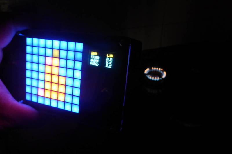
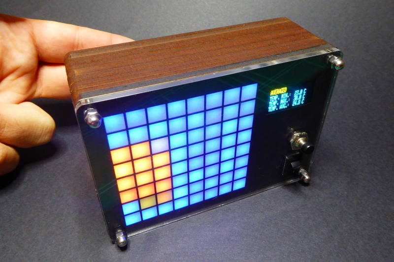
So what do you have if you throw in a box an IR sensor and a LED matrix, add a small microcontroller, a LiIon battery and a charger and a step-up to power the LEDs? Well, in my case the outcome has been a bulky but nice camera (albeit a very poor resolution one).
I know there are commercially available IR Cameras like this one [Ebay]. They have 300k pixels and can overlay a normal image over the IR image and other fancy stuff, but they are also more expensive (around 200€ the best deal) and waaaaaay less fun to build.
Wires all around
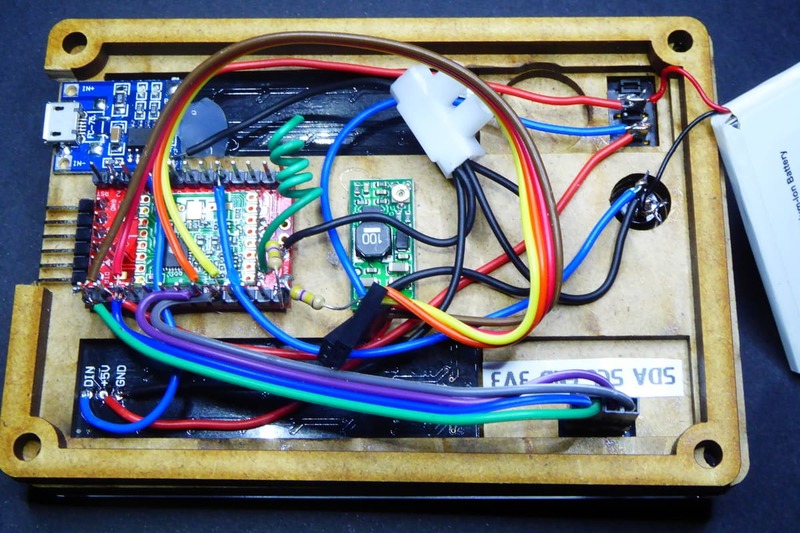
Unlike most of my projects, which are mostly single board or stacked boards projects, this time I went for the truly maker-like wire mess. And I did some really nasty stuff with the iron.
Let me first summarize the BOM (just for the electronics):
| Component | Buy | Price |
|---|---|---|
| TP4056-based LiIon battery charger | Aliexpress / Ebay | 1.68€ |
| 850mAh LiIon battery | Ebay | 3.42€ |
| Switch | Aliexpress / Ebay | 0.20€ |
| Pololu Adjustable Boost Regulator 2.5-9.5V | Pololu | 10.68€ |
| Moteino | LowPowerLabs | 11.58€ |
| Pushbutton | Aliexpress / Ebay | 0.16€ |
| uOLED I2C display | Aliexpress / Ebay | 6.69€ |
| 8x8 WS2812 matrix | Aliexpress / Ebay | 6.74€ |
| Panasonic Grid-EYE AMG8833 | Farnell | 18.26€ |
| Tinkerman AMG88XX Breakout board (unit price buying 3) | OSH Park | 1.50€ |
| Total | 60.91€ |
Adding the wood (maybe 5€) and the acrylic (maybe 2€) the total budget is under 70€.
The only small microcontroller that could do the job and I had available was a Moteino by LowPowerLabs. I use these arduino spin-offs for my sensors at home, they bundle a RFM69 radio by HopeRF and are very low power. Problem is that this particular one had the headers soldered on and it was really a mess to weld cables to them.
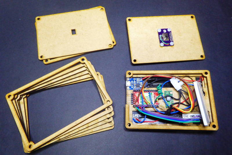
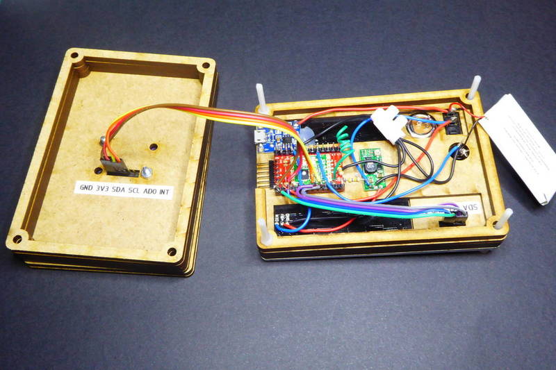
I even soldered the battery wires directly to the connectors. Don't really think it's a good idea but it worked. I did some rough calculations about the battery. The most power hungry component is, of course, the LED matrix. An experimental measure with the display at low brightness (16 over 255) gave about 140mA. So the 850mAh battery I'm using should last for around 6 hours. Not much but at least we are not talking in the minutes time scale.

The battery is connected to a generic charger module based on the TP4056 [datasheet, pdf]. A switch sits in the middle of these two and the rest of the circuit. So if you connect a cable to charge the battery it will charge it even if the camera is switched off.
From the switch on there are two power circuits. The first one goes to the VIN pin in the Moteino that expects at least 3.6V. The MCP1703 [datasheet, pdf] LDO regulator then power the microcontroller and also the uOLED display and the AMG88 module. The later expects 3V minimum to operate and the voltage dropout in the MCP1703 is 0.65V. Again that set the battery threshold in 3.65V.
The second power circuit is a Pololu step up that outputs 5V and up to 2A from as low as 2.5V. These 5V are used to power the LED matrix which might use a few hundred mA.
Purple rain
Second reference to Prince in less than a month. This time it's an allegory to OSH-Park (purple boards) and crying (rain).
You might have noticed in the pictures that the AMG88 module I'm using is not the one from Tindie I talked about. The module from Tindie is (roughly) 55€ including shipping to Barcelona. I found out I could buy the sensor alone for as low as 19.93€ from Arrow Electronics (no longer available individually, check Farnell although it's out-of-stock right now) and since I had other stuff to buy I reached the minimum for free shipping. Customs was another story. But still those (almost) 20€ plus the 5€ per 3 pieces from OSH-Park looked like a great deal.
The board was pretty straight forward. The datasheet contains information about the “recommended” external circuit with only 7 passives including I2C pull-up resistors. So I openend Eagle(I'm commiting myself to use KiCad in the future) and had a board in no time.
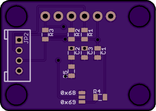
That was three weeks ago. This week I received the boards and started soldering the sensor. I was afraid it was going to be hard to solder the AMG8833 but it resulted in an easy task after all. Until I grabbed my continuity tester. Damn! SDA, SCL and AD0 lines were not connected. Reflowed the tin with a bit more of heat but still nothing. Then I noticed a weird mark on the board, checked the other two and f**k. Those traces are gone!
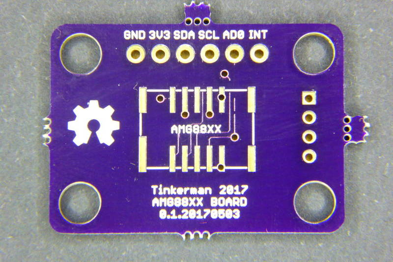
So I went back to Eagle to check the design rules and there were 9 errors. What was I thinking of? The I got it, I had been doing another board for SeeedStudio and forgot to change the DRU file. Indeed the board had no errors with the design rules for SeeedStudio 2 layers. My bad…
But I was not going to throw to the bin a 20€ (or 40€) sensor just because of this error. So…
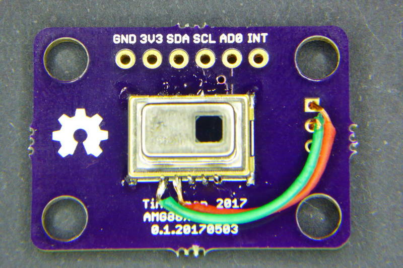
The module from OSH Park I linked in the BOM is version 0.2.20170529, not tested but I made the traces thicker and changed a few vias so now it passes the DRU check. You can also grab the Eagle files and send it yourself to fab.
The AMG88XX board is released under the Creative Commons Attribution-ShareAlike 3.0 Unported License (CC-BY-SA 3.0) and follows the terms of the OSHW (Open-source hardware) Statement of Principles 1.0. It can be checked out at my grideye repository on Github.
A room for the eye
I'm having fun lately making sliced boxes inspired in Pimoroni PiBow enclosure for the Raspberry Pi. The box is based on different layers (slices) of materials (acrilyc, cardboard, paper and MDF) stacked one on top of the other with room in between to house the different components.
These slices are:
- a transparent acrylic front-face;
- a black thin cardboard mask;
- a white paper acting as diffusor;
- a 4mm MDF grid that houses each LED in its own cubicle;
- a 2.5mm MDF cast for the LED matrix PCB;
- a 2.5mm MDF as support for the matrix PCB and uOLED board;
- several (5) 4mm MDF hollow layers to house the electronics;
- a 2.5mm MDF as support for the AMG88XX board;
- a 4mm MDF hollow layers to house the AMG88XX board;
- and a 2.5mm MDF as a back pane with a hole for the IR sensor
I use OpenSCAD to design programmatically the different layers. Here you have some renders of the different layers with some space in between to allow an insight of the inside.
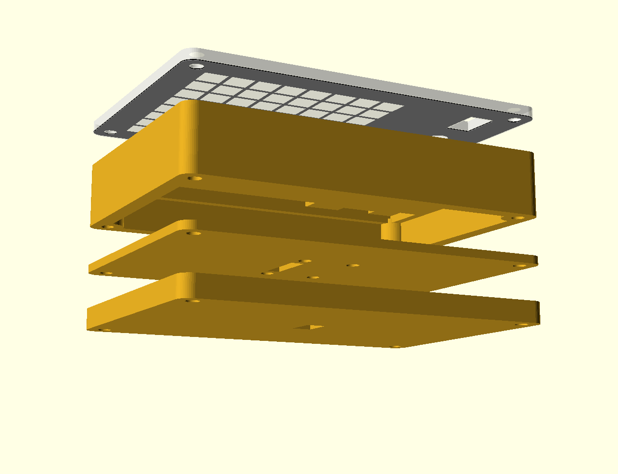
Initially I planned to add a 2.1x5.5mm jack in the front pane to charge the device but finnally I decied to use the microUSB connector of the charging board and openen a side “window” with my exacto knife in one of the slices to reach the connector and to program the microcontroller via FTDI.
And some code
The GridEye Camera firmware is released as **free open software **and can be checked out at my grideye repository on Github.
The code for the Moteino is under the “code” folder in the repository and is ready to be built (dependencies included) using PlatformIO.
Access the AMG8833 registers
Using the AMG8833 sensor via I2C is a piece of cake. The maximum refresh rate as per datasheet is 10Hz and you have plenty of time to dump all the contents, do the calculations and update the LED matrix. Check the “amg8833.ino” file in the “code/src” folder for a complete example but here you have the method that does all the heavy lifting.
void amgLoop() {

    static unsigned long last = 0;
    if (millis() - last < AMG8833_UPDATE_INTERVAL) return;
    last = millis();

    // Get the register contents
    for (unsigned char start=0; start<128; start+=16) {
        readBytes(AMG8833_ADDRESS, AMG8833_DATA01L + start, 16, &_rawData[start]);
    }

    // Calculations
    float min = 1000;
    float max = 0;
    float avg = 0;
    float temperatures[64]; // Contains the calculated temperatures of each pixel in the array
    for (unsigned int i = 0; i < MATRIX_WIDTH * MATRIX_HEIGHT; i++) {
        temperatures[i] = (float) ((_rawData[2*i + 1] << 8) | _rawData[2*i]); if (temperatures[i] > 2047) temperatures[i] = temperatures[i] - 4096.0f;
        temperatures[i] *= 0.25f; // scale to get temperatures in degrees C
        avg += temperatures[i];
        if (temperatures[i] > max) max = temperatures[i];
        if (temperatures[i] < min) min = temperatures[i];
    }
    _minTemperature = min;
    _maxTemperature = max;
    avg /= (MATRIX_WIDTH * MATRIX_HEIGHT);
    _avgTemperature = avg;

    // Show matrix
    matrixClear();
    for (int y=0; y<MATRIX_HEIGHT; y++){
        for (int x=0; x<MATRIX_WIDTH; x++){
            CRGB color = getColor(getPattern(), temperatures[y+x*MATRIX_WIDTH], min, max, avg);
            matrixSetPixelColor(x, y, color);
        }
    }
    matrixShow();

}
As you can see, the code is executed every AMG8833_UPDATE_INTERVAL milliseconds (that's set to 100ms, so it will sample at max speed, 10Hz). It first dumps the contents of the registers via I2C. Then performs some calculations to get temperature values for each cell in the array as well as minimum, maximum and average temperatures. And finally it updates the display using a “getColor” method that maps a temperature to an RGB.
Color patterns
The code supports different color patterns (that's the getColor method before). Right now and averaged pattern and a subset of that called “Human” are implemented.
The averaged color pattern is based on the great Grid-Eye Thermal Camera Demo by Pure Engineering (they also sell a module for the AMG8833, by the way). This patterns shows the values above average as reddish and those below as blueish. The intensity of the color will depend on the temperature. Since the average depends on the sample images from different objects are not comparable.
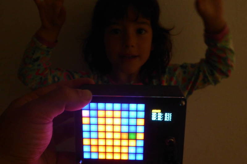
The “human” color pattern fixes the values (minimum, maximum and average temperatures) to match a typical human body heat as seen by the sensor.
CRGB ColorPatternAveraged(float temperature, float min, float max, float avg) {

    uint8_t r = 0;
    uint8_t g = 0;
    uint8_t b = 0;

    g = map(temperature, min, max, 0, 75);

    if (temperature > avg) {
        r = map(temperature, min, max, 0, 255);
    } else if (temperature < avg) {
        b = map(temperature, min, max, 0, 255);
    }

    return CRGB(r, g, b);

}

CRGB ColorPatternHuman(float temperature, float min, float max, float avg) {
    min = 20;
    max = 34; // 31
    avg = 30; // 26
    temperature = constrain(temperature, min, max);
    return ColorPatternAveraged(temperature, min, max, avg);
}
A state machine for the display
At boot, the OLED display shows the current color pattern, the battery voltage (via a resistor divider tied to A0) and the minimum, maximum and average temperatures reported by the AMG8833.
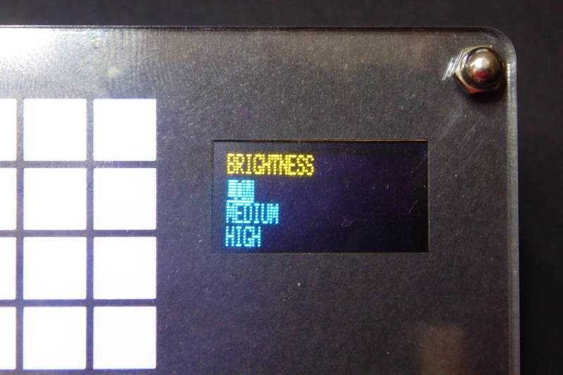
You can use the button to change to different settings pages by double clicking it. Right now only “color pattern” and “brightness” pages are implemented. Inside a given page you can click the button to change the value of the setting (“averaged” or “human” for color patterns, “low”, “medium” or “high” for brightness). Double clicking in the brightness page will take you back to the normal display showing the info.
Could this be a wireless camera?
There are still some other functionalities I'd like to add to this IR camera. Adding more color patterns is one of them but the most interesting one is maybe trying to send the readings wirelessly to a computer. Remeber I'm using a Moteino with an RFM69? it will be great to be able to see the same images on your computer display (like in the video before by Pure Engineering). But it will also be very interesting to be able to record thermal changes over time, like a mug cooling down…
But the truth is that the microcontroller is running out of memory, so I might have to do some trickery to make it work and maybe the refresh rate will have to be lower. Will try and will let you know.
"Grid-eye camera (sliced, of course)" was first posted on 28 May 2017 by Xose Pérez on tinkerman.cat under Code, Projects, Tutorial and tagged amg88, amg8833, arrow electroics, farnell, ftdi, github, grideye, hoperf, i2c, ir, led matrix, lipo battery, mcp1703, moteino, oled, openscad, oshpark, panasonic, pibow, pimoroni, platformio, pololu, pure engineering, rfm69, seeedstudio, slices, tindie, tp4056, ws2812.