Geiger Counter
My last project is a über-cool Geiger-Muller Counter.

Hardware: Radio Hobby Store Geiger Counter Radiation DIY Kit (second edition)
Some weeks ago I suffered a radioactivity fever, so to speak. I backed the APOC Mini Radiation Detector at Kickstarter and also bought a Geiger Counter Radiation Detector DIY Kit from Radio Hobby Store at Ebay. The former has finished the funding with more than 11 times the pledged amount. The later arrived home some 10 days ago, so I just started playing with it.
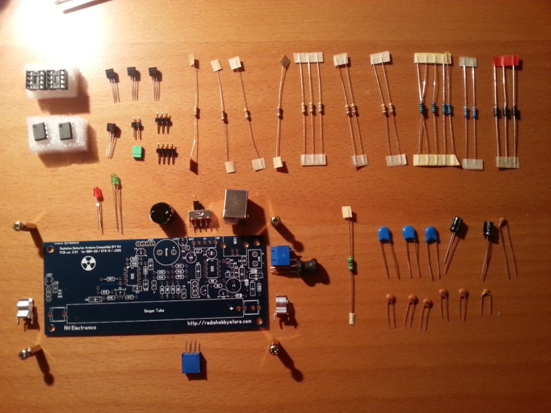
The kit comes unassembled but every part is through hole and really easy to solder. The kit contains everything to get a basic Geiger Counter except for the SBM-20 Geiger-Muller tube, but those are easy to find at Ebay also and mine arrived just one day after the kit. Once assembled you get a Geiger counter that can be powered with 5V through USB or a terminal block and it beeps and flashes a LED every time a beta o gamma particle enters the tube… But, you also get a VCC and GND pins and an interrupt pin (labelled INT) to power and monitor the counts with your favourite controller. And that's fun!
To build the kit follow the seller's advice: take your time and enjoy. It has a bunch of parts but none is too hard to solder. It took me about an hour. The only problem I had was with IPA. IPA, or Isopropyl Alcohol (C3H7OH), is used to clean electronic boards and components. The people at Radio Hobby Store emphasize the use of IPA after soldering to wash any flux or any other potentially problematic residue since the board uses high voltage (~400V). Even thou my board was quite clean after the soldering I followed their advice.
It took me a couple of phone call and a one hour trip to get a bottle of IPA 99% in Barcelona… I've read you can find the in some drugstores but the one I was after had a a spray which I found very convenient. So I applied the IPA and is was a mess. I ended up with a cover of metal (?) dirt all over the board… It took me a while to clean it up again and check that nothing was desoldered or disconnected. I don't know what happened but it was completely unexpected. My guess is that it had something to do with the type of solder I use (lead-free), but again I don't know.
I need to know more about what IPA is useful for and how it actuates before trying it again. Alcohols might not be that dangerous but playing with chemicals requires a deeper understanding of what you are doing.
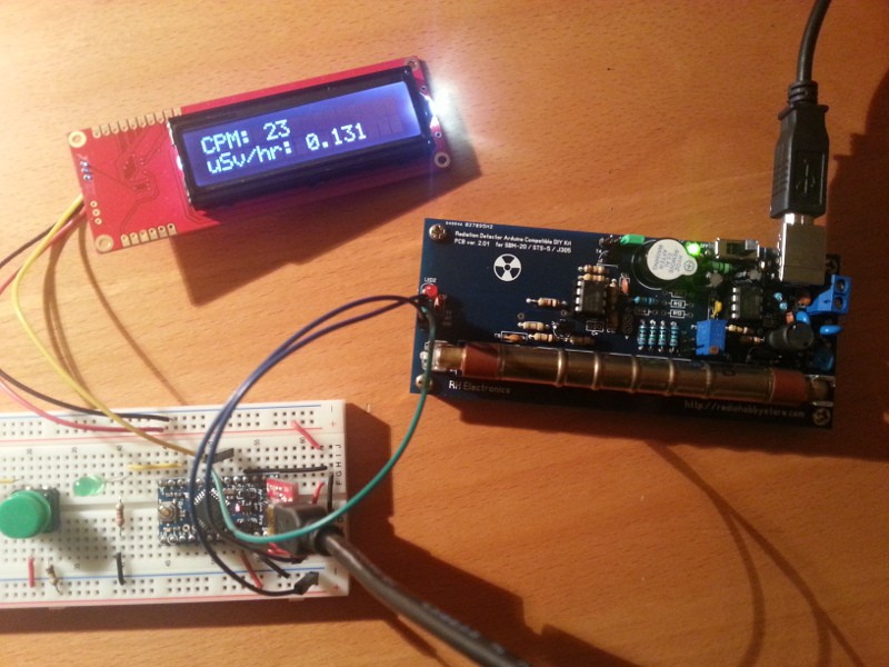
Anyway, after this trouble the board worked as it should. I calibrated the blue pot to get around 400V across the Geiger tube, switched it off, unplugged, installed the tube and plugged it again. Then, with an imaginary sound of drums, I switched it on and it began beeping! Yes!
Hardware: The Controller
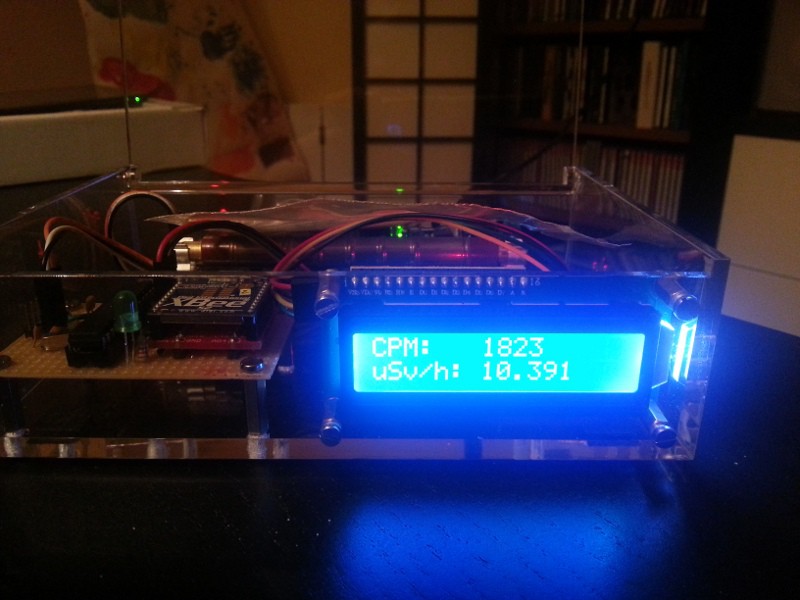
I prototyped the counter with an Arduino Pro Mini and a Sparkfun Serial Enabled 16x2 LCD which uses simple serial commands to write characters on the LCD. Everything is 5V except for the Arduino but the LCD works with 3V3 TTL signals so no problem.
The first prototype was really easy to assemble. I had it working in less than half an hour, including a first version of the code to count and display the data on the LCD.
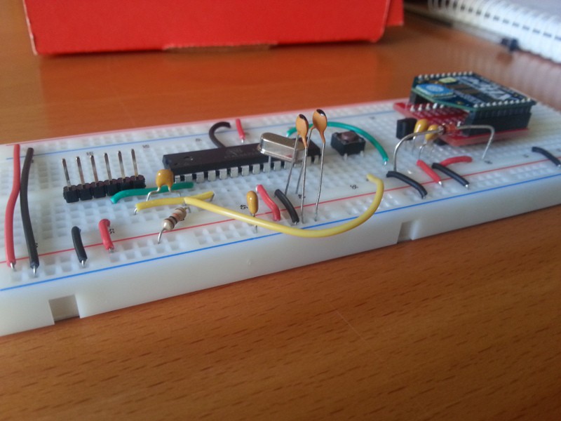
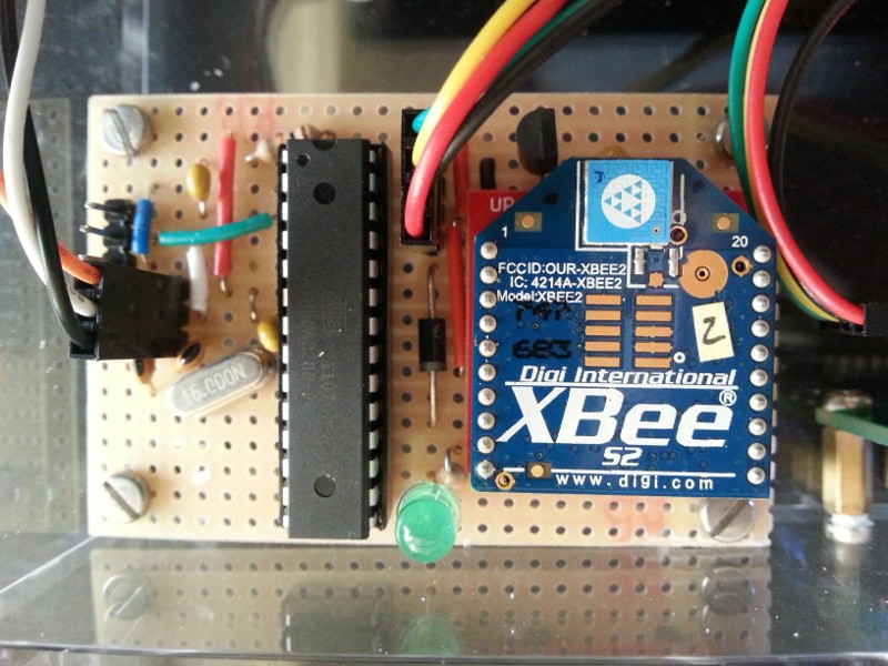
The first evolution was to substitute the Arduino Pro Mini with a bare ATmega328P, the very same micro but in a cheaper and bulkier package. I prototyped this second version in a breadboard adding the XBee. Now, the ATmega328P is 5V but the XBee is only 3V3. A TSC295033 linear voltage regulator lowers the voltage to 3V3 to power the radio and a diode and a pull-up resistor protect de DIN line. When the input is LOW the diode is transparent and the DIN pin of the radio sees the LOW and the resistor is dissipating ~10mW. When the input is HIGH (5V) the diode blocks the current and the resistor pulls up the line to 3V3.
I used a Zener in the first prototype and took the picture below before realising my mistake and replaced it with a 1N5819 Schottky diode. The Zener was a BZX85C 3V3, so it was permanently in avalanche breakdown. In fact you can use a Zener but in a different configuration, check Rob Faludi's post about Xbee level shifting.
Level shifting is a great topic to learn basic stuff about electronics. Whenever there is a question on any forum about this there are tens of different answers. Just give a try to some of them!

This is the first project where I use this level shifting technique. I had used the simple resistor divider in other projects before (like the Rentalito) but the resistors slow down the signal and can be a problem when using higher baud rates. Also, my first idea was to use the XBee internal pull-ups for level shifting instead of an external one but finally I opted for the second option because the 30K pull-up was too high and resulted in a less than 3V HIGH value in the DIN input. A 1K2 external resistor solved this problem and removed the dependency on configuration.
Finally I moved everything to a stripboard. To design the stripboard I used VeeCAD, a stripboard editor, and it really helped me. There was little room inside the box and my first design was too big. It would have been a nightmare to erase and redraw everything several times in paper but in the computer everything was simpler and I could play with different designs until I found the one that was both clean and small. The free version is good enough to design anything on a stripboard but the commercial version (26.26 USD) adds some goodies that can make the difference: color, net tracing and the ability to place elements diagonally.
But, I made a mistake. I crossed the RX and TX lines between the controller and the FTDI header and I didn't realize it until I tried to reprogram the chip. Anyway it was easy to fix and in the layout below, generated with VeeCAD, this mistake has been fixed.
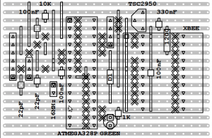
The real thing, note the fix for the RX/TX mistake:
Hardware: The LCD
Sparkfun's Serial LCD is really easy to use, but I wanted to give a chance to some cheap LCDs and I2C serial boards I had recently bought at Ebay. I had already done some tests the night I received them. The seller provides a library and some sample code but I was not able to make it work and I quitted to go to bed.
So this was a second chance to make the think work. The boards I had bought to drive the LCD were I2C serial interface boards (just search for “IIC/I2C/TWI/SPI Serial Interface Board Module” at Ebay). These boards use a PCF8574, an 8 bit I/O expander with I2C interface, basically it lets you drive the LCD with just 2 wires for power and ground and 2 more for data (SDA) and clock (SCL).
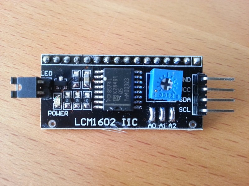
None of the libraries for Arduino I tested worked with the board. After googling a bit I found a thread on the Arduino Forum where a user (Riva, thanks!) had found out that the connections were not what the library he was using expected. So I grabbed the tester, put it in continuity mode, and checked what connections led where. The library I wanted to use (NewLiquidCrystal) has a constructor where you can explicitly define the pins so I just instantiated my LCD object with the right pin assignments and voilà.
The initialization code for the LCD is as follows:
// Thanks to Riva for pointing out the wrong pin order
// http://arduino.cc/forum/index.php?topic=164722.0
// 0 -> RS
// 1 -> RW
// 2 -> EN
// 3 -> LED
// 4 -> D4
// 5 -> D5
// 6 -> D6
// 7 -> D7
//
// Constructor with backlight control
// LiquidCrystal_I2C(uint8_t lcd_Addr, uint8_t En, uint8_t Rw, uint8_t Rs,.
//                  uint8_t d4, uint8_t d5, uint8_t d6, uint8_t d7,
//                  uint8_t backlighPin, t_backlighPol pol);

LiquidCrystal_I2C lcd(0x20, 2, 1, 0, 4, 5, 6, 7, 3, POSITIVE);
Hardware: The Box
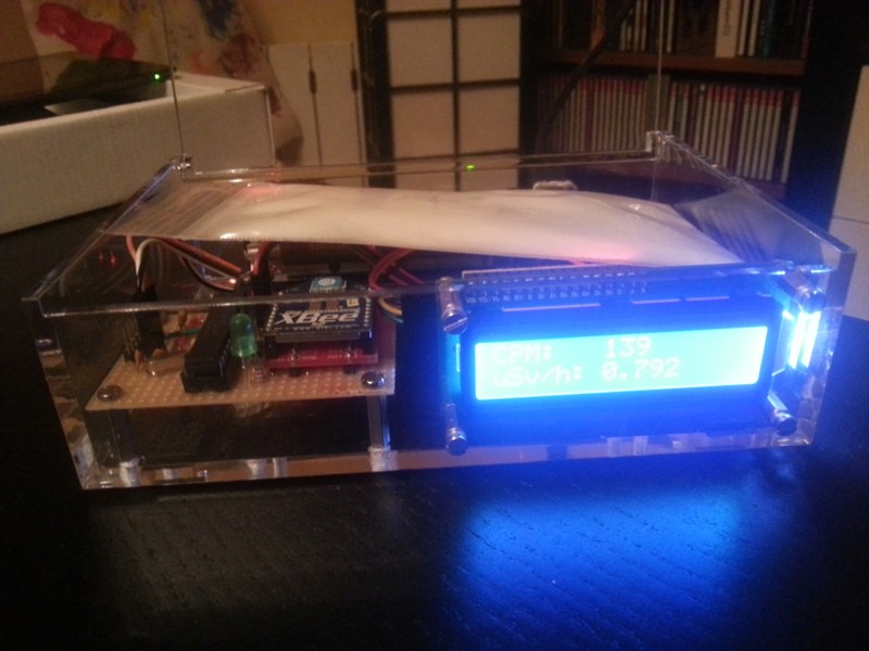
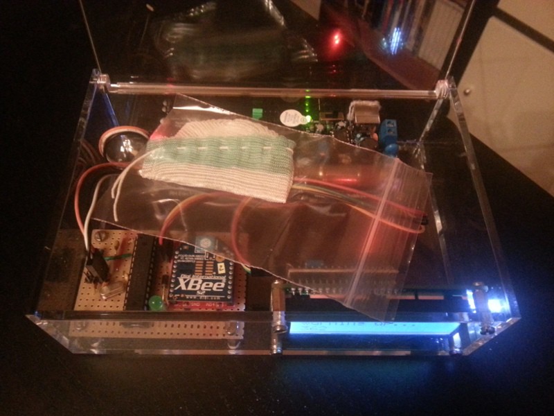
I happened to have the perfect box for this project. It is transparent, elegant and everything fits inside like if it was designed for the project. The only trouble was finding a way to place the cables so they do not cover the tube or the radio antennae.

Software
The code is very simple. There are only a couple of things worth noticing: the LCD connection mentioned before and the ring buffer implemented to store partial readings. The reason for the ring buffer is that I wanted to update the display more often than once every minute with a “moving sum” of counts.
Basically there are 10 cells that store partial counts. Every 6 seconds the code stores the current pulses count value in a cell of the ring, overwriting the previous value. So the sum of the cells values is the count value for the last 60 seconds. To avoid having to sum all the cells on every update, the sum gets updated before pushing the new value to the cell by subtracting the current value for that cell and adding the new one.
// calculate the moving sum of counts
cpm = cpm - ring[pointer] + pulses;

// store the current period value
ring[pointer] = pulses;

// reset the interrupt counter
pulses = 0;

// move the pointer to the next position in the ring
pointer = (pointer + 1) % UPDATES_PER_PERIOD;
That's it. There isn't much more to say. As always, the code, schematics and other documentation, are available at github.
One last thing about the software: I have started using Ino Toolkit for this project. If you have it installed you can run “ino build” from the code folder to get the binaries. I don't like the Arduino IDE: it is very feature limited, the editor is clumsy and the whole thing is too heavy. I've always used different command line tools like ed.am Arduino Makefile. My first impressions are good, it has better library discovery capabilities but I missed the “make size” command to know how much free space left you have to code more features…
Testing it!
I was going to add some theory explaining the different types of radiation, how a Geiger-Muller tube works and some reference levels but there are plenty of pages on the internet about the subject and I will not add anything new. Instead I can recommend you to read this tutorial that the people from Cooking Hacks have put together for their Arduino geiger counter shield.
There are a number of natural radioactivity sources. The first of them being the background radiation which you will always get. With my detector this background radiation averages 26 CPM over long periods (more than one day). Then you have some commonly available sources like smoke alarms, some paint used in pottery, luminous displays from old watches or compasses, gas mantles or anything with potassium, like some low-sodium kitchen salt or even bananas.

This low-sodium salt is the easiest to find in Barcelona (apart from bananas) so I just went to the supermarket and bought a tin of LoSalt “The Original” (sic). Then I poured some salt on a self-sealing bag and put it over the Geiger-Muller tube. In any given sample, every 8547 atoms of potassium there is one isotope of 40K, which is radioactive. Potassium 40 is a very interesting isotope, it represents the largest source of radioactivity in human body and has a half-life of 1,250·109 years (if you have a sample of 40K, after one thousand million years only half of its atoms will have gone through a radioactive decay). The counts with the potassium salt bag near the tube raised to almost 139 CPM on average over a 10 minutes record. That is more than 5 times the background noise…
To get a higher count sample I went to Ebay and bought one Thorium Latern Mantle or Gas Mantle. Funny enough, even though these mantles were pretty common here 20 years ago I had to go to an USA supplier to get one. These mantles are impregnated with thorium dioxide to produce a brighter white light. They were retired, mainly because the safety concerns for people involved in the manufacture. Thorium (232Th) is a radioactive element, part of the Thorium decay chain which undergoes several alpha and beta decays until it stabilizes as Lead (208Pb). The test with the Thorium Mantle was impressive. The seller said the set of mantles he had read between 1100 and 2100 CPM. Mine read an average of 1662 CPM over a 5 minutes test but wrapping it around the tube I got up to 1903 CPM.
I repeated the tests isolating the gas mantle (it was already inside a plastic bag) from the counter with a paper first and then with a couple of layers of aluminium foil. The experiment set up was not quite right because the readings with the paper were about a 33% lower than without it and that makes no sense since the paper would have blocked only alpha radiation and the tube is sensitive to beta and gamma. Nevertheless I think it is worth it to post here the results. In the graphic below, the first bump is the Potassium salt sample, the second is the thorium gas mantle only with the plastic cover, then with the paper and then with the aluminium foil.
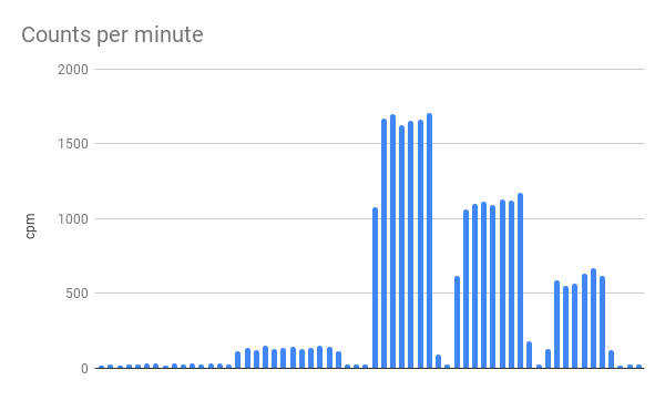
The first bump is due to a sample of KCl, the second, third and forth bumps are a Thorium Gas Mantle with plastic, paper and aluminium foil shielding.
Of course, the sensor is also reporting to my home MQTT network and then the readings are sent to Cosm Xively in almost real-time, here you have the last 24 hours of readings but it doesn't work anymore.
"Geiger Counter" was first posted on 23 May 2013 by Xose Pérez on tinkerman.cat under Code, Learning, Projects and tagged arduino, atmega328, background radiation, banana, geiger counter, ipa, level shifting, mqtt, pcf8574, potassium, radioactivity, sbm-20, serial lcd, stripboard, thorium, veecad, xively.