GeekWorm Power Pack Hat Hack
Sorry for the tongue twister ;)
I've been somewhat busy lately and it's been a long time since my last post. I have a few projects on the go but not much time to sit down and write about them… Let's see if this one goes through…
I've been lately looking for a reliable UPS system for Raspberry Pi 3. I moved my home server to a RPi a few months ago and even thou its behind an ACS UPS a couple of other projects involving RPis required mobility (one of them) and unassisted power backup (the other). So I started browsing several marketplaces looking for a solution.
Update: heads up on Joachim's work
Joachim Baumann's is working on an Raspberry Pi UPS based on the same Geekworm UPS hat that offers very interesting features, including:
- configuration sync between the ATTiny and the Raspberry
- temperature measurement for monitoring the battery temperature
- communication using I2C, thus not blocking any pins of the Raspberry Pi
- minimal modification of existing hardware
- automatic shutdown and restart
- different thresholds for warning, hard shutdown and restart
- external button to execute configurable functionality
- measurement of an additional external voltage
I strongly recommend you to check his work: https://github.com/jbaumann/attiny_daemon
Some “available” solutions
There are some (not many) solutions out there. I had a few requirements and some goods-to-have. Initially price was not an issue and that was good since that allowed me to focus on the features:
- Hat form factor (I wasn't looking for a USB power bank)
- Capable to deliver power to the Raspberry Pi while charging
- Capable to deliver enough power for a Raspberry Pi 3 running several services (but headless)
- Battery monitoring from the OS
- RTC (nice to have)
- Compatible with LiPo batteries, other chemistries as a bonus
I don't want to favor one solution over another. But the UPS PIco HV 3.0 might be the best option “available”, and I quote “available” because it's out of stock everywhere I have checked. It sells for about USB 34, supports LiPo and LiFePO4 batteries, delivers up to 3A, has battery monitoring, RTC and a zillion of other goodies. There is also the LiFePO4wered/Pi3. It is not a RPi hat but it's small enough. Supports only LiFePO4 batteries and lacks RTC. Sells for USD 42.
Of course these two products are not backed by big companies but by good professionals that have probably designed them to solve a need they had. And at some point they thought there was a market niche here. Actually both of them are on Tindie.
Perfect is the enemy of good
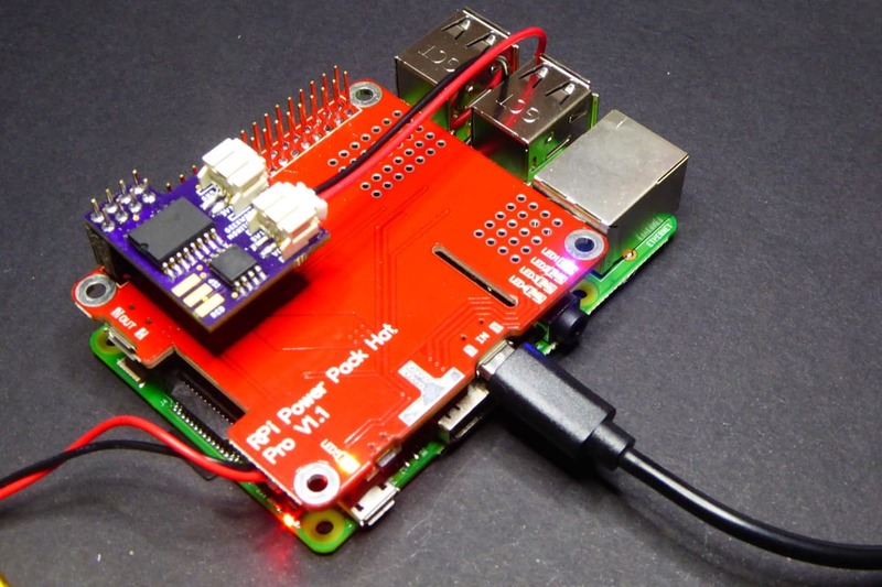
The UPS PIco was almost perfect but I just couldn't find a way to buy it. So when I found the UPS Power Pack by GeekWorm that was less than USD 16 (without battery) I thought it was not too risky to give it a try.
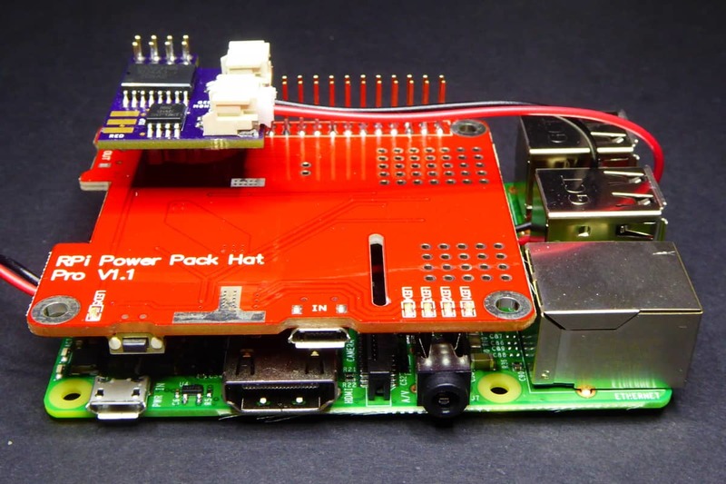
It supports LiPo batteries, you can use the Raspberry Pi while charging and it can deliver up to 2A (1.4A while charging). It provides an I2C interface to check the battery charge status from the OS and support hot unplug. There is little information provided by the manufacturer but the people at raspberrypiwiki.com have gathered some info about it.
You can buy a GeekWorm Power Pack Pro v1.1 without battery [Ebay] for less than 15€ or with a 2500mA LiPo battery [Ebay] for 22.5€.
With a little help from my friends
The Geekworm Power Pack Pro has a main issue. It has two power output modes: via the secondary micro USB connector or via the GPIO and, incomprehensibly, the first one is the default output. That means that even thou the board “boots” when power is applied (for instance after a power blackout) it won't power the Raspberry Pi until you long click the side button.
What were they thinking about? This ruins the whole purpose of the hat.
Fine. This required some help. I needed a way to set the hat into GPIO output power mode automatically and, since we are “improving” the hat, why not adding an RTC and maybe a way to power a secondary device.
This last point was a requirement in one of the projects I was working on: I needed a way to power cycle a Texas Instruments SensorTag because I needed it in “discoverable” mode so the Raspberry Pi could connect to it. The SensorTag enters “discoverable” mode on boot or when you click one of the side buttons.
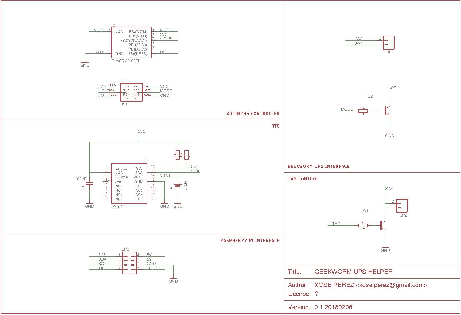
Let me introduce you the GeekWorm monitor. It sports an ATTiny85 that monitors the hat power supply and the RPi 3V3 pin and changes the power output mode if the Raspberry Pi is not being powered.
But that's not everything. It also monitors a specific GPIO of the RPi and expects a HIGH there. If it's not it allows 3 minutes in case the Raspberry Pi is booting before power cycling it. This is necessary because in the event that a powerdown is executed by the OS the Raspberry Pi won't boot by itself unless it's power supply is reset.
Imagine you are running on batteries (no external power) and the OS detects the battery is running low and it executes a preventive power down to avoid data corruption. But then power comes back and the battery is charging again and we would like to resume operations. The ATTiny85 will notice the Raspberry Pi is not running and will want to reset it. The only way to reboot the RPi is to disconnect it and reconnect it. Well, changing the power output mode to USB and back to GPIO does just that.
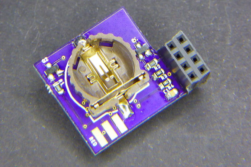
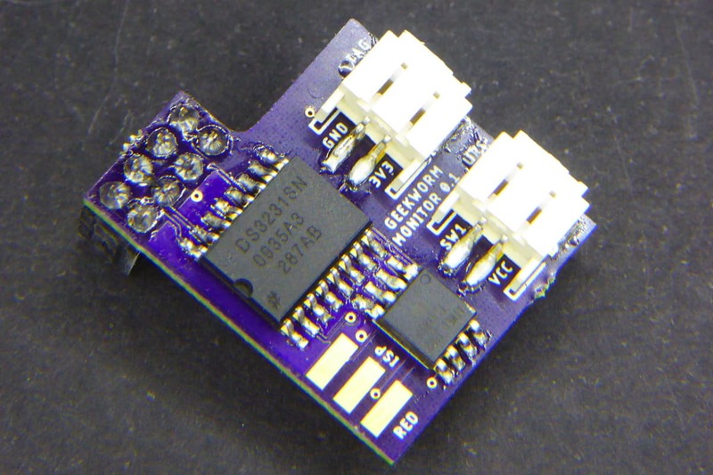
Finally the board also features a DS3231 RTC backed by a coin cell and a secondary connector to power an external device via a MOSFET driven by the Raspberry Pi.
You might have notice the purple. Yes, you can order the GeekWorm Monitor from OSH Park.
Normal operation
Let me summarize the operation:
- Under normal circumstances, the USB cable will be connected to the hat power input at all times, powering and charging the LiPo unless there is a power outage.
- If that happens the battery will start powering the Raspberry Pi immediately so it won't reset. And the battery will start discharging…
- At this point the Raspberry Pi is monitoring the battery charge level via I2C and might decide to shutdown to prevent data corruption
- Eventually power will be back and the battery will start charging but the Power Pack is not powering the RPi
- The ATTiny85 gets its power from the 5V input line of the hat, so it wakes and checks the Raspberry Pi 3V3 pin and it reads low.
- The ATTiny85 pushed the button line to ground and changes the power output mode
- It will wait up to 3 minutes for a certain GPIO to be asserted true before changing the power output mode (and go back to 5).
- If the pin is asserted HIGH then everything is OK. The ATTiny85 will keep on monitoring the pin in case it goes low for whatever reason.
The GeekWorm Monitor
The ATTiny85
The ATTiny85 is powered by the input 5V. This is very convenient since it sets the operation in a well known state: “I'm awake, so the battery is charging, so the Raspberry Pi should be running”.
Changing the power output mode is done pushing down the button line via a transistor for 5s effectively emulating a button push. The ATTiny85 will do that if it detects the Raspberry Pi is not being powered or when it needs to power cycle it.
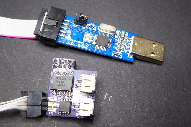
Flashing the ATTiny85 is done using a USB like the one below (you can buy it here USBASP Programmer [Ebay]). You might remember I used the same “edge connector” with my Solr project.
The code is very straight forward.
#include <Arduino.h>

#define MODE_GPIO           0       // Connected to the Geekworm mode button
#define POWER_GPIO          1       // Connected to the RPi 3V3
#define RUNNING_GPIO        2       // Connected to the RPi GPIO set at local.rc

#define CHECK_DELAY         5000    // Run check every 5 seconds
#define CHECK_RUNNING       36      // Check RPi GPIO every 36 delays (3 minutes)
#define CHANGE_MODE_DELAY   5000    // Hold mode button down for 5 seconds

unsigned int count = 0;

void pressButton() {
    digitalWrite(MODE_GPIO, HIGH);
    delay(CHANGE_MODE_DELAY);
    digitalWrite(MODE_GPIO, LOW);
    count = 0;
}

void setup() {
    pinMode(MODE_GPIO, OUTPUT);
    pinMode(POWER_GPIO, INPUT);
    pinMode(RUNNING_GPIO, INPUT);
    digitalWrite(MODE_GPIO, LOW);
}

void loop() {

    // Every X seconds
    delay(CHECK_DELAY);

    // Check if RPi3 is being powered
    bool powered = digitalRead(POWER_GPIO) == HIGH;

    // Change mode if RPi3 is not being powered
    if (!powered) pressButton();

    // Every X delays
    count = (count + 1) % CHECK_RUNNING;
    if (0 == count) {

        // Check GPIO
        bool idle = digitalRead(RUNNING_GPIO) == LOW;

        // Press button if GPIO is not HIGH
        // If switching off,
        // loop will switch it on again after CHECK_DELAY seconds
        // efectively resetting the RPi
        if (idle) pressButton();

    }

}
Saying I'm alive
I said the ATTiny85 is monitoring the 3V3 pin to know if the Raspberry Pi is being powered but it's also monitoring a GPIO to know if it's actually running. It expects a HIGH value there and will wait 3 minutes to see it before rebooting the RPi.
Forcing the Raspberry Pi to output a HIGH in a certain GPIO is very easy and does not require any special language or library, you just have to use the /sys/class/gpio path. Edit the /etc/rc.local file and add this contents before the exit line:
echo 14 > /sys/class/gpio/export
echo out > /sys/class/gpio/gpio14/direction
echo 1 > /sys/class/gpio/gpio14/value
Monitoring the battery
I used a python script supervised with supervisor to monitor the battery level and power down the Raspberry PI if it goes below a certain threshold for a certain time. Since the code is too long (and includes several files) to copy it here I have created a Gist with it here: Geekworm battery monitor script. The only dependency is ruamel.yaml to read the YAML configuration file.
Note that the code is conservative and requires two different conditions to perform a power down:
- The battery level must be below a certain threshold
- The battery must have been continuously discharging for a certain amount of time
If either of this two conditions becomes false the power down is not executed or cancelled.
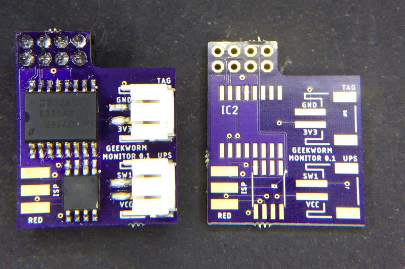
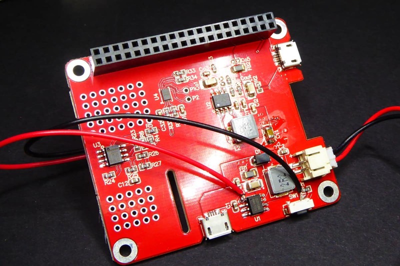
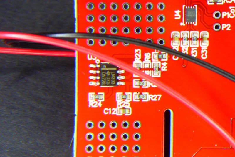
Prototyping zones?
Just a side note so you don't do the same mistake I did. Do you see those two prototyping zones in the board?
"GeekWorm Power Pack Hat Hack" was first posted on 09 April 2018 by Xose Pérez on tinkerman.cat under Hacking, Projects and tagged attiny85, ds3231, geekworm, hat, lipo, mosfet, oshpark, raspberry pi, rtc, sensortag, ups, usbasp.