EEPROM Rotation for ESP8266 and ESP32
The Arduino Core for ESP8266 and ESP32 uses one SPI flash memory sector to emulate an EEPROM. When you initialize the EEPROM object (calling begin) it reads the contents of the sector into a memory buffer. Reading a writing is done over that in-memory buffer. Whenever you call commit it write the contents back to the flash sector.
Due to the nature of this flash memory (NOR) a full sector erase must be done prior to write any new data. If a power failure (intended or not) happens during this process the sector data is lost.
Also, writing data to a NOR memory can be done byte by byte but only to change a 1 to a 0. The only way to turn 0s to 1s is to perform a sector erase which turns all memory positions in that sector to 1. But sector erasing must be done in full sectors, thus wearing out the flash memory faster.
How can we overcome these problems?
EEPROM rotation
These days I've been working on a standalone library that wraps the stock EEPROM library and does “sector rotation". Using more than one sector (a sector pool) to store data and keeping track of the one with the latest valid information.
The library overwrites two methods of the original one: begin and commit. The begin method will load the data from all the sectors in the sector pool one after the other trying to figure out which one has the latest valid information. To do this it checks two values:
-
A 2-bytes CRC
-
A 1-byte auto-increment number
These values are stored in a certain position in the sector (at the very beginning by default but the user can choose another position with the offset method).
The CRC is calculated based on the contents of the sector (except for those special 3 bytes). If the calculated CRC matches that stored in the sector then the library checks the auto-increment and selects the sector with the most recent number (taking overflows into account, of course).
Those special values are stored by the overwritten commit method prior to the actual commit.
With every commit, the library will hop to the next sector. This way, in case of a power failure in the middle of a commit, the CRC for that sector will fail and the library will use the data in the latest known-good sector.
EEPROM_Rotate API
The EEPROM_Rotate library for ESP8266 Arduino Core is released under the Lesser General Public License 3.0 (LGPL-3.0) as free open software and can be checked out at my EEPROM_Rotate repository on GitHub.
The library inherits form the Arduino Core for ESP8266 EEPROM library, and it shares the same API. You can just replace one with the other. The same public methods with the same signature. By default it will use the same sector as with the EEPROM library (sector 1019 for 4Mb boards, sector 251 for 1Mb boards), or you can specify another sector in the constructor. It can behave like a drop-in replacement.
If you define a sector pool size different that one (using the size method). The other sectors are the ones counting from the base one downwards. This means that if we set up a sector pool size of 4 for a 4Mb board using default base sector, the used sectors will be 1019, 1018, 1017 and 1016.
An example would be:
EEPROM_Rotate EEPROM;           // Instantiate the object
EEPROM.size(2);                 // Use two sectors for rotation
EEPROM.begin(4096);             // Use the full sector size to store data
uint8_t data = EEPROM.read(10); // Read a byte at address 10 in the memory buffer
EEPROM.write(data + 1);         // Increase the value
EEPROM.commit();                // Persist data to flash (in a different sector)
Disabling the original global EEPROM object
The original EEPROM library automatically instantiates an EEPROM object that's already available to use. This consumes little memory (since the data buffer is only created and populated when calling begin). But anyway if you don't want to have a unused object around you can disable the object instantiation by using the NO_GLOBAL_EEPROM build flag.
OTA (and non-OTA) upgrades
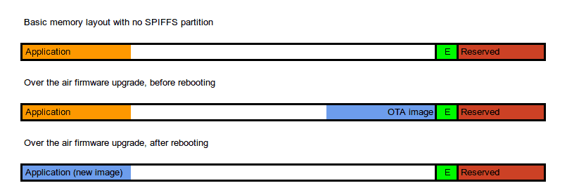
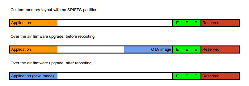
You can use custom memory layouts (see next section) to “reserve” memory sectors for EEPROM rotating like in the section before. But there is no need for it as long as you take some precautions. Basically, if are using more than one sector and you have not reserved them, all of them but the last will be overwritten when doing an OTA upgrade, because OTA images are first stored at the end of the firmware block.


On both cases all but the last sector get overwritten by the OTA image. What can you do?
Well, the library has a special method called backup that will backup the contents of the current memory buffer to any given sector. If you call it with no parameters it will save them to the last sector in the pool, the one that's safe from OTA.
So, whenever you do an OTA upgrade (being it firmware or the SPIFFS image) call the backup() method first. The ArduinoOTA library has a onStart callback you can use to backup the contents. Same for the Update class.
There is still one special case that could be a problem: non-OTA upgrades. In a wired upgrade the firmware has no control of the situation and it cannot backup the EEPROM before the upgrade. If your image is large enough it may overwrite the sectors in use for the EEPROM pool. For a firmware image this is very unlikely, only with old 512Kb memory chips you may run into problems when flashing big images.
But when flashing the file system you will always hit this problem, because it always overwrites the full SPIFFS partition. So if you are flashing the SPIFFS partition and want to keep the EEPROM configuration you have two options: a custom memory layout that really reserves more sectors for EEPROM (see below) or upgrade it always over the air and program your firmware so it first backs up the EEPROM contents to the latest sector using backup.
Custom memory layout and auto-discover pool size
Using a custom memory layout could be a good solution to be sure that the information in your sector pool never gets overwritten. Moreover, the library will automatically discover the number of available sectors for EEPROM. These will be the number of sectors after the SPIFFS memory space (or after the application partition if no SPIFFS partition) except for the last 4 (reserved by Espressif).

/* Flash Split for 1M chips */
/* sketch 999KB */
/* eeprom 20KB */

MEMORY
{
  dport0_0_seg :                        org = 0x3FF00000, len = 0x10
  dram0_0_seg :                         org = 0x3FFE8000, len = 0x14000
  iram1_0_seg :                         org = 0x40100000, len = 0x8000
  irom0_0_seg :                         org = 0x40201010, len = 0xf9ff0
}

PROVIDE ( _SPIFFS_start = 0x402FB000 );
PROVIDE ( _SPIFFS_end = 0x402FB000 );
PROVIDE ( _SPIFFS_page = 0x0 );
PROVIDE ( _SPIFFS_block = 0x0 );

INCLUDE "../ld/eagle.app.v6.common.ld"
Program memory is mapped at 0x40200000, so a 1Mb flash memory ends at 0x40300000. Here you can see the end of the SPIFFS block is at 0x402FB000. So there are 20480 bytes after that point. Every sector has 4096 bytes so thats 5 sectors. Given that the last four are reserved there is one left for EEPROM.
Now let's see this custom layout:
/* Flash Split for 4M chips */
/* sketch 1019KB */
/* spiffs 3040KB */
/* eeprom 16KB */
/* reserved 16KB */

MEMORY
{
  dport0_0_seg :                        org = 0x3FF00000, len = 0x10
  dram0_0_seg :                         org = 0x3FFE8000, len = 0x14000
  iram1_0_seg :                         org = 0x40100000, len = 0x8000
  irom0_0_seg :                         org = 0x40201010, len = 0xfeff0
}

PROVIDE ( _SPIFFS_start = 0x40300000 );
PROVIDE ( _SPIFFS_end = 0x405F8000 );
PROVIDE ( _SPIFFS_page = 0x100 );
PROVIDE ( _SPIFFS_block = 0x2000 );

INCLUDE "eagle.app.v6.common.ld"
Now this is a 4Mb board (like the in the ESP12 modules). Flash memory ends at (0x40200000 + 4 * _1024 * _1024) 0x40600000. Therefore, after the SPIFFS block there are still 32768 bytes or 8 sectors. 4 of them are reserved, so 4 more are available to rotate the EEPROM contents.
ESP32 Partition table
The library for the ESP32 works very much the same way but there are some differences due to the way the stock EEPROM for ESP32 library works. This library (in practice) requires a custom partition table to work. You could use any partition in the default partition scheme but you will want to create a custom one defining as many partitions for EEPROM as you'd like to.
This is not difficult at all, using PlatformIO. If anyone knows how to do it with the Arduino IDE (not touching the core files) then, please, let me know.
PlatformIO
PlatformIO lets you define a CSV file for each environment in your platformio.ini file. Like this:
[env:nano32]
platform = espressif32
board = nano32
framework = arduino
board_build.partitions = partition-table.csv
build_flags = -DNO_GLOBAL_EEPROM
This CSV file defines the different partitions in the SPI flash memory:
# Name,   Type, SubType, Offset,  Size, Flags
nvs,      data, nvs,     0x9000,  0x5000,
otadata,  data, ota,     0xe000,  0x2000,
app0,     app,  ota_0,   0x10000, 0x140000,
app1,     app,  ota_1,   0x150000,0x140000,
eeprom0,  data, 0x99,    0x290000,0x1000,
eeprom1,  data, 0x99,    0x291000,0x1000,
spiffs,   data, spiffs,  0x292000,0x16E000,
Here you can see that we have added two partitions for EEPROM (eeprom0 and eeprom1).
EEPROM32_Rotate API
The EEPROM32_Rotate library for ESP32 Arduino Core is released under the Lesser General Public License 3.0 (LGPL-3.0) as free open software and can be checked out at my EEPROM32_Rotate repository on GitHub.
The library inherits form the Arduino Core for ESP32 EEPROM library, but it uses a slightly different API. Differences are in the constructor. The original EEPROM library for ESP32 has different constructor signatures but only valid at the moment is:
EEPROMClass EEPROM("eeprom0");
To make this library API more consistent, I have decided to change the way you create and ‘populate’ an object:
EEPROM32_Rotate EEPROM;
EEPROM.add_by_name("eeprom0");
Now you may find obvious how to add more partitions to the pool:
EEPROM32_Rotate EEPROM;
EEPROM.add_by_name("eeprom0");
EEPROM.add_by_name("eeprom1");
EEPROM.add_by_name("eeprom2");
EEPROM.add_by_name("eeprom3");
Actually, if all partitions have the same data subtype (usually 0x99, thou this is only a convention) then it's a lot easier to add them all:
EEPROM32_Rotate EEPROM;
EEPROM.add_by_subtype(0x99);
Now you can use it like a regular EEPROM object:
EEPROM32_Rotate EEPROM;
EEPROM.add_by_subtype(0x99);
uint8_t b = EEPROM.read(0);
EEPROM.write(0, b+1);
EEPROM.commit();
Remember than the stock EEPROM library for ESP32 has a bunch of convenient methods like readLong, readBytes, writeString,… you can also use those!
"EEPROM Rotation for ESP8266 and ESP32" was first posted on 04 June 2018 by Xose Pérez on tinkerman.cat under Code, Tutorial and tagged arduino, eeprom, esp32, esp8266, memory, memory layout, meory partitions, ota, rotation, spi flash memory.