Connected power meter
A few weeks ago a user came with a request to add support in ESPurna to a power meter that had been hacked by Karl Hagström. It is a very cheap chinese power meter with plenty of room on the inside, enough to house an ESP8266 module and a DC/DC power supply and the main IC protocol had been reverse engeneered. There even was a repository by the Harringay Maker Space with sample code for an arduino compatible platform.
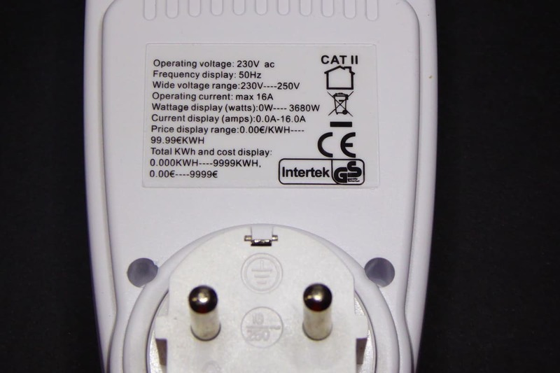
I found it really interesting so I jumped in and ordered two of them (for 25,20 euros in total). Unfortunately the seller I bought it from has ran out of them. But you can still find them on the usual market places, like these ones [Ebay] or (also with non-EU variants) these ones [Aliexpress].
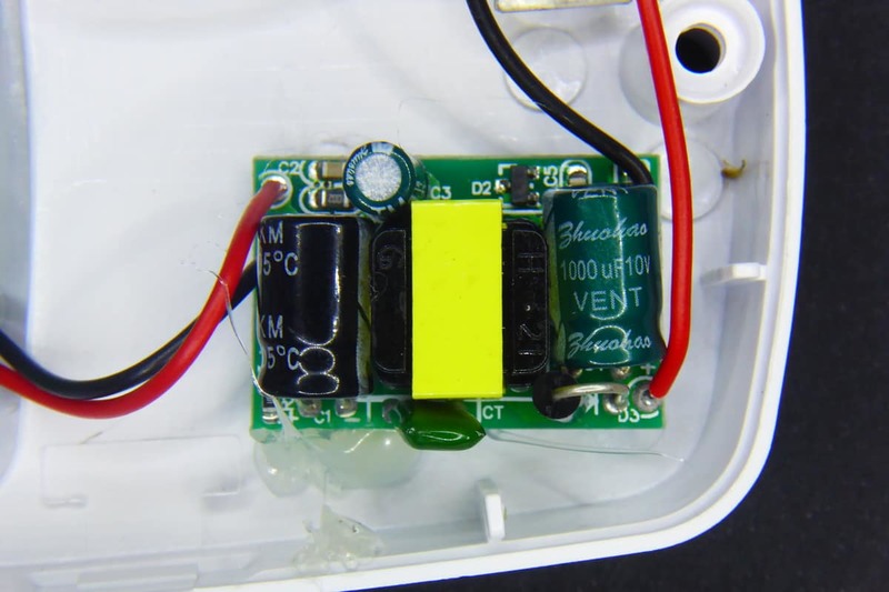
When I received them I quicky unscrewed the enclosure of one of them and… wow, it looked slightly different than that on Karl's post but also different from the one the people at Harringay Maker Space had worked with.
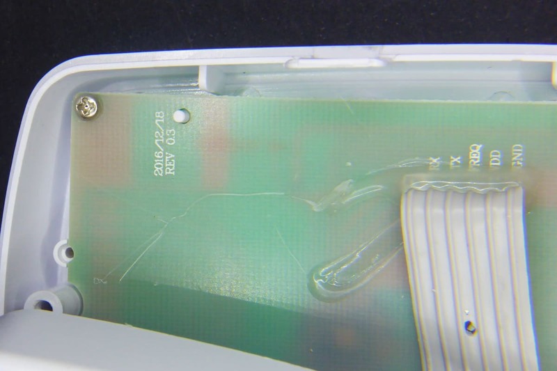
I went back and forth and I noticed the hack was almost 2 years old and the board was clearly different: different version (unlabelled on Karl's pictures, version 2014-04-28 on Harringay's power meter and 2016-12-18 on mine), different board layout with a different connector between the power meter board and the display (7 wires on theirs, 6 on mine). But the most important difference was the main power meter IC. Karl had reverse engineered the ECH1560 on his power meter, a 24pin SOP package (on the back on his device, on the front in Herringay's power meter). Mine was only 16pin…
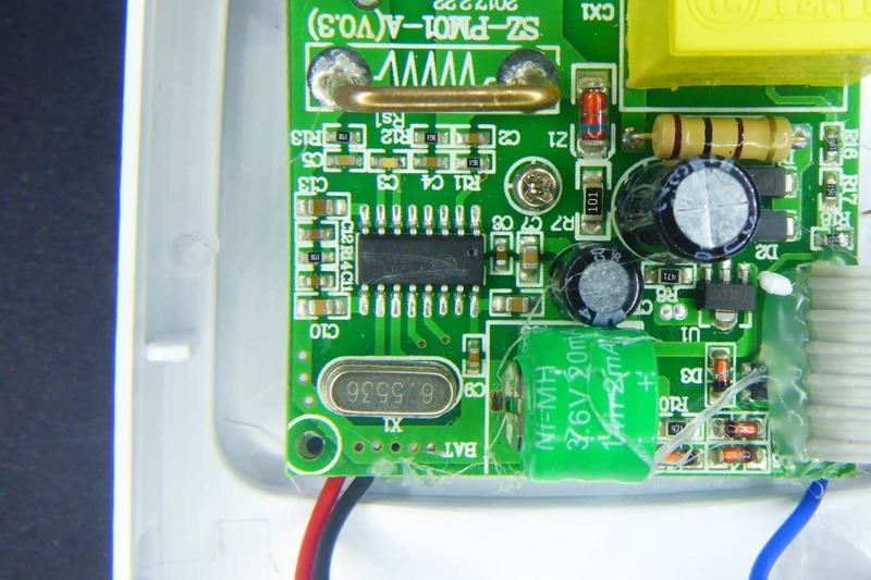
I had to decipher the IC mark using parts from both devices since the manufacturer had crossed out the marks (they don't want us to hack it or what?). Finally my best guess was V9261F. I quicky googled it and… bingo!
You will (almost) never be the first one
The Domoticz community is quite active. And they were already working on supporting this device. Actually the datasheet for the Vango V9261F [datasheet, PDF] is public (contrary to that on the ECH1560). So I just had to “borrow” the work from two of the domoticz community members (kudos to Kapee and Rolo) and continue from there.
The hack, like with Karl's method, is based on sniffing the traffic between the power board (where the V9261F sits) and the display board. On this new version there are 6 cables labelled (RX, TX, FREQ, VDD and GND, the sixth is unlabelled). So it strongly looked like being a serial interface. All they had to do was to wire the TX pin to a GPIO in the ESP8266 module and use a software serial library to receive the messages.
The messages looked something like this:
FE 11 01 04 00 00 01 1D
FE 11 04 6B E5 FF FF 74 BF FF FF 70 5C E2 3A 00 30 02 00 86
There are two messages there, both are responses to a read operation. The first one returns 1 register (each register in the V9261F has 4 bytes) and thus has 3 bytes for the header, 4 bytes for the register and 1 more byte for the checksum, totalling 8 bytes. The other response contains 4 registers and has (3+4*4+1) 20 bytes. The key here was knowing what registers where those. Unfortunatelly the response does not specifiy the register address, only the contents. But as easy as sniffing the TX line, one can sniff the RX line. This is what the microcontroller in the display board requests to the V96261F:
FE 11 80 01 00 00 00 A2
FE 11 19 04 00 00 00 06
Great, so it first requests the SysCtrl register (0x0180, not very useful for us) and then 4 registers starting with 0x0119. What registers are those? Let's check the datasheet:
- 0x0119: Average total active power
- 0x011A: Average total reactive power
- 0x011B: Average total voltage RMS
- 0x011C: Average total current RMS
So good :)
Wire it
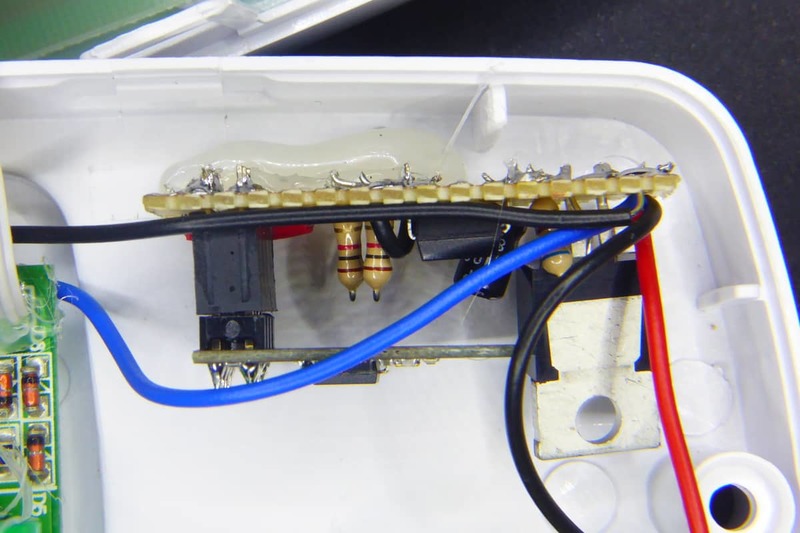
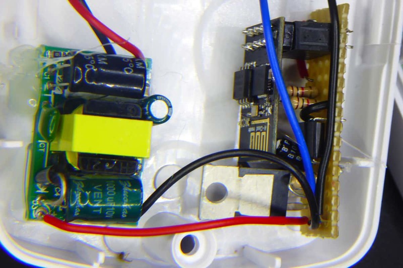
Rolo, at the Domoticz forum has shared a schematic to isolate the TX pin from the ESP8266 module using a PC817 optocoupler [Ebay]. I thought it was a good oportunity to use those “old” ESP01 modules I never use so I prepared a stripboard using his schematic as starting point.
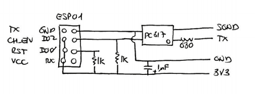
The schematic assumes you power it with a 3V3 source. In the first term I used a 5V source so I had to add a AMS1117-3V3 to the power input. Anything capable of supplying 400mA peak should be enough.
For the second powermeter I used a wemos board, which simplifies the connections. Basically you just need the optocoupler and the input resistor.
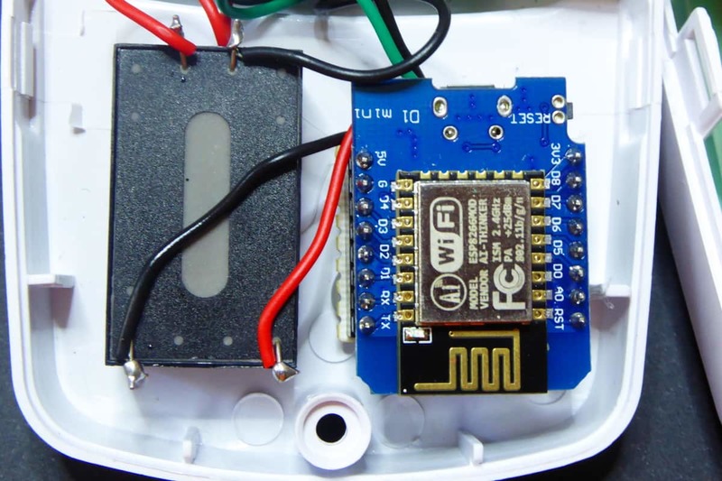
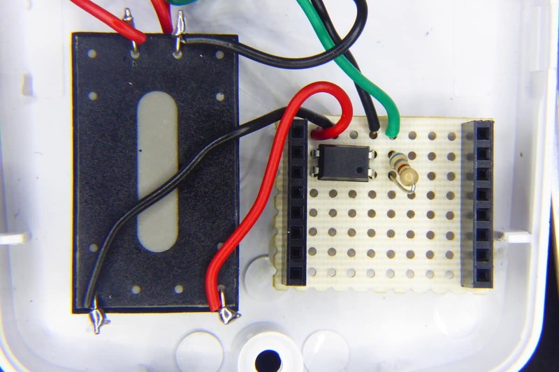
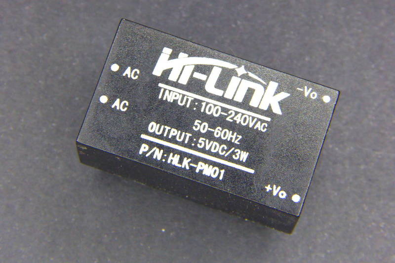
You might have noticed I also used two different power sources. Again, you will need 400mA output to be safe. HLK-PM01 [Aliexpress] modules are great for that, but cheaper “open” AC/DC 5V 700mA power supply modules [Aliexpress] will also work.
It is very important that you double check the connections and the weldings. Also, once you have tested it and you want to close the box, hot glue everything so they stay in place. Trust me. You don't want a wire going loose there.
Support in ESPurna
The ESPurna firmware is released as **free open software **and can be checked out at my Espurna repository on GitHub.
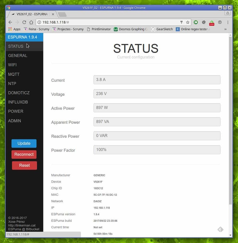
Final step was to integrate the code in ESPurna, so it will benefit from other “goodies” in the firmware (MQTT, REST API, Home Assistant and Domoticz support, WebUI, WiFi configuration, etc). The firmware reports “real time” values (every 6 seconds) to the web client and aggregated (and filtered) values via MQTT to other services.
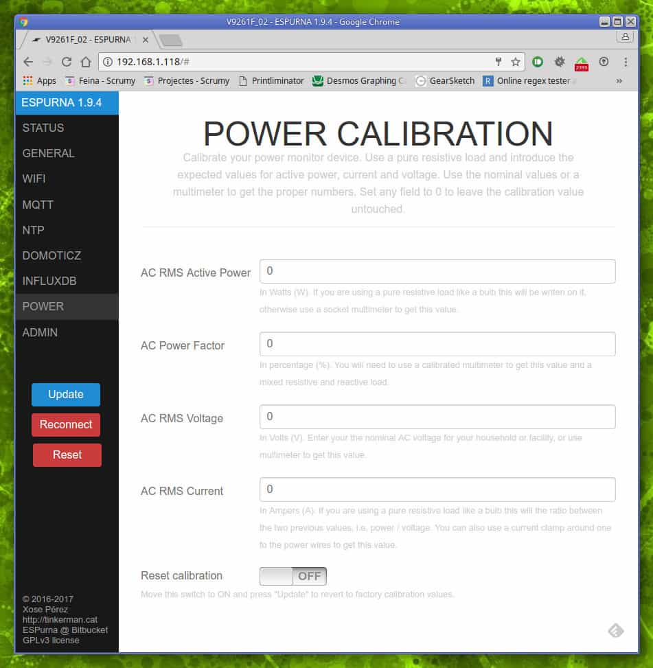
But one bonus that comes with ESPurna is the calibration feature. Because there are some calculations involved in getting the power value from the number the V9261F provides. Same for current or voltage. And there are some “magic numbers” on those calculations. I have not been able to find out what those numbers should be. In section 5.13 of the datasheet talks about calibration registers and formulae but I can't figure the numbers out…
So instead you can use the power section in the Web UI to calibrate the values you are getting. You are not supposed to write there those “magic numbers”. Instead, you have to write the values the power meter is displaying on the screen and the firmware will do the maths for you.
But, what about the ECH1560?
Yeah! That was the first idea. I decided to add support for the ECH1560 in ESPurna too. But this is completely untested and it will almost certainly have bugs. So if you want to give it a try, be ready to debug.
You will have to wire two cables now, instead of one. One for the CLK pin and the other for the MISO line. Use optocouplers too, you'll stay safer. There is already a device in ESPurna for the ECH1560 (called GENERIC_ECH1560) that assumes the CLK pin is on GPIO4 and MISO on GPIO5. If your setup is different you might want to change the definitions in the hardware.h file:
// -----------------------------------------------------------------------------
// ECH1560
// -----------------------------------------------------------------------------

#elif defined(GENERIC_ECH1560)

    // Info
    #define MANUFACTURER        "GENERIC"
    #define DEVICE              "ECH1560"

    // ECH1560
    #define POWER_PROVIDER      POWER_PROVIDER_ECH1560
    #define ECH1560_CLK_PIN     4
    #define ECH1560_MISO_PIN    5
    #define ECH1560_INVERTED    0
Also, some people has reported their power values are inverted. If you are getting weird power values try changing the ECH1560_INVERTED setting to 1.
Good luck and report back!
"Connected power meter" was first posted on 24 September 2017 by Xose Pérez on tinkerman.cat under Hacking, Projects and tagged ams1117, domoticz, ech1560, esp01, esp8266, espurna, hlk-pm01, home assistant, optocoupler, power meter, power monitor, rest, v9261f.