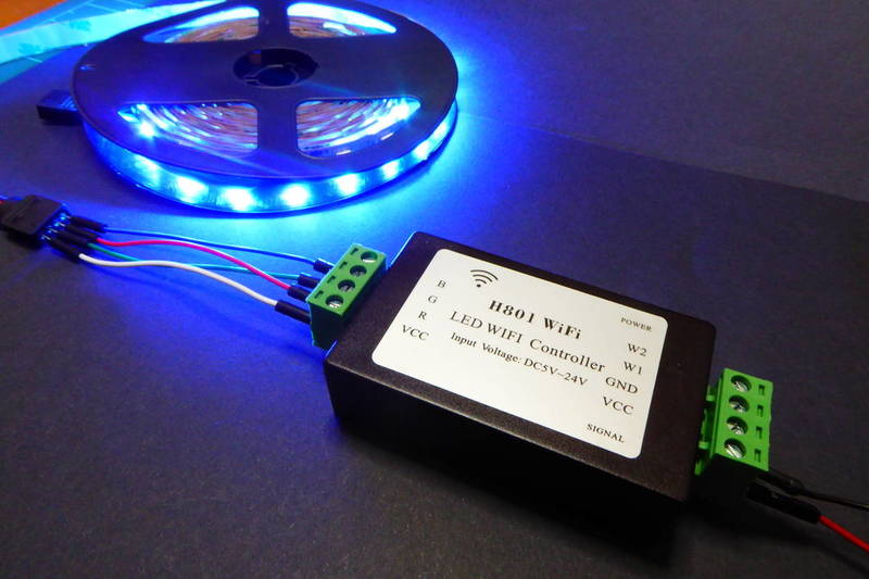
A closer look at the H801 LED WiFi Controller
Some weeks ago I talked about the Magic Home LED Controller as I was adding support for it in my ESPurna firmware. At the time a user pointed me to the H801 Led WiFi Controller by Huacanxing. The user in question (Minh Phuong Ly) even did a pull request with some preliminary support for it. So I decided to give it a go.
The H801 is a 5 channels controller that you can find for about 9-10€ at Ebay or Aliexpress. It's slighly more expensive than the Magic Home Led Controller (you can find the later for 7€ at Aliexpress) but it also is quite different from the insides…
The outsides
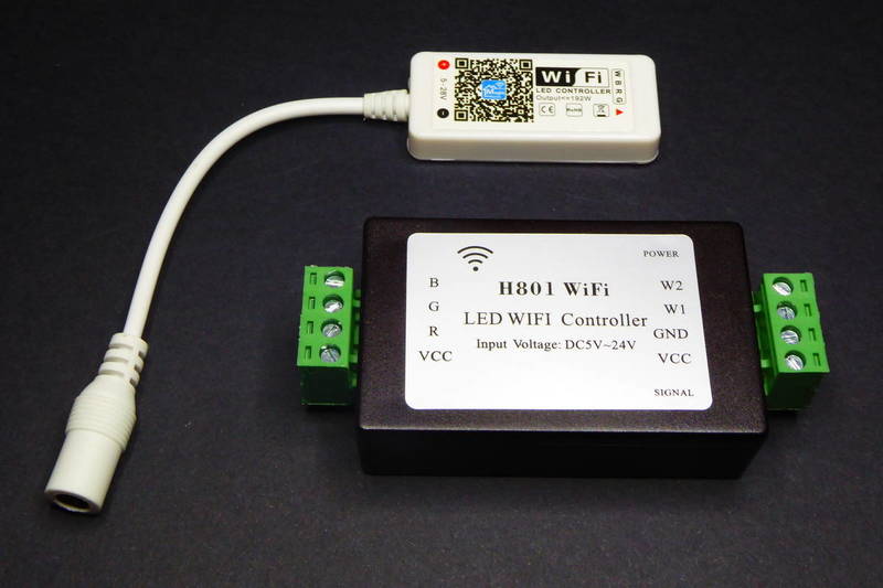
The first thing you notice is that this is quite bigger than the one by Magic Home. The later has also more “common” connectors both for power supply (the typical 2.1x5.5mm jack) and the strip connector since most have the same 4 lines for each channel (red, green and blue) and the common anode for power. The H801 uses screw terminals for every connection, input GND and VCC and the five channels (red, green, blue and two whites) and also the common anode.
So the Magic Home is more ready for plug and play while the H801 is a more adaptative solution.
The insides
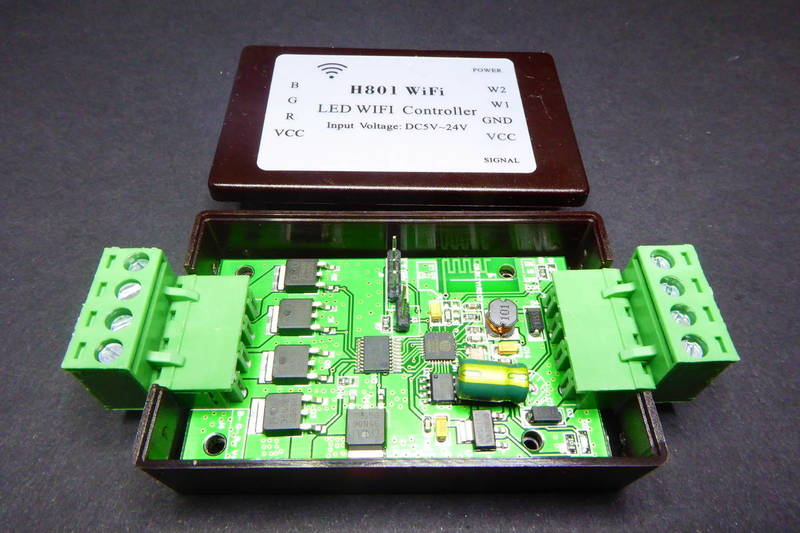
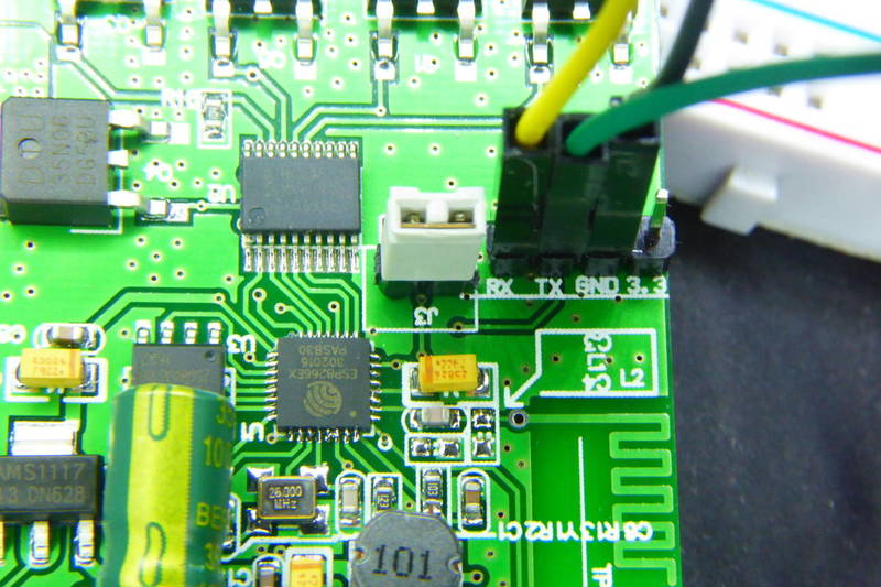
The H801 has four philips screws in the back and once you remove them you gain access to the insides of the controller. Things to notice: each channel is driven by a beefy DTU35N06 [pdf, datasheet]** **by Din-Tek, a 60V N-channel mosfet in a TO-252 package. These are rated 35A or 106W maximum power disipation and they use quite some space on the board, with thick traces running to the terminals. The ESP8266 interfaces the mosfets via an NXPHC245 DTU35N06 [pdf, datasheet] bus transceiver that does the level shifting.
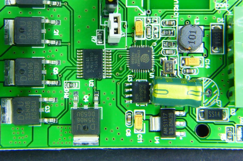
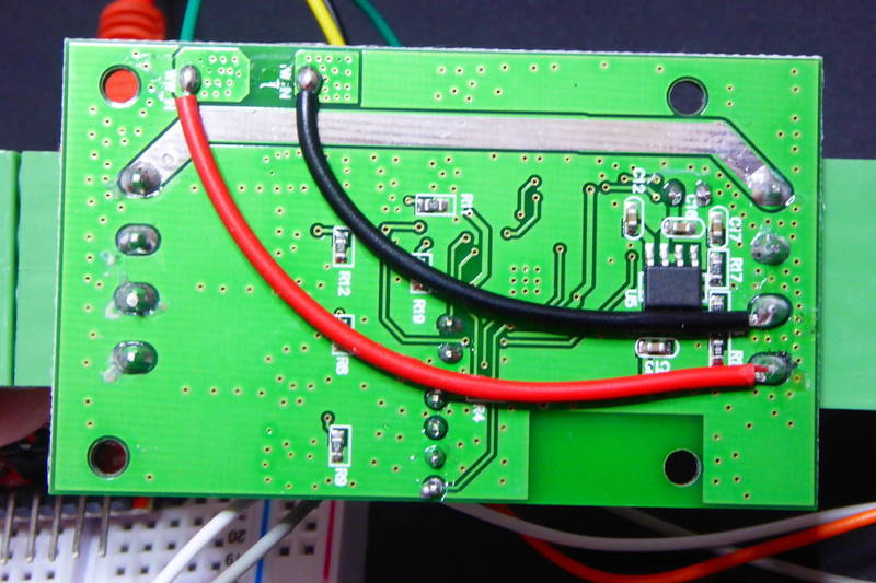
The W1 and W2 lines are routed back to the terminal using wires on the back, I guess the ran out of space in the PCB. Also on the back there is a AOZ1212AI [pdf, datasheet] to lower it further down to 3V3 for the ESP8266.
All in all it looks more roomy. Even thou I don't know what mosfets the Magic Home Led Controller uses they are SOT-23 packages. The ones in the H801 look more solid. But the specs for both controllers are the same (according to some sources): 48W per channel. I'm not sure I would use 4A per channel on my 12V strips with the Magic Home controller, but I might try with the H801.
Flashing it
Another good thing the H801 has it that it exposes the required GPIOs for firmware flashing in an easy way, not the small pads in the Magic Home controller. There is a header with 3V3, GND, RX and TX labeled and a jumper to tie GPIO0 to ground when you want to boot into flash mode.
ESPurna firmware supports H801 since version 1.8.0. It is defined by default as a 5-channels device (LIGHT_PROVIDER_RGB2W). If you want to use it with a standard RGB LED strip you might want to change the light provider to LIGHT_PROVIDER_RGB in the hardware.h file.
// -----------------------------------------------------------------------------
// HUACANXING H801
// -----------------------------------------------------------------------------

#elif defined(H801_LED_CONTROLLER)

    #define MANUFACTURER        "HUACANXING"
    #define DEVICE              "H801"
    #define LED1_PIN            5
    #define LED1_PIN_INVERSE    1
    #define RELAY_PROVIDER      RELAY_PROVIDER_LIGHT
    #define LIGHT_PROVIDER      LIGHT_PROVIDER_RGB2W

    #undef RGBW_INVERSE_LOGIC
    #undef RGBW_RED_PIN
    #undef RGBW_GREEN_PIN
    #undef RGBW_BLUE_PIN
    #undef RGBW_WHITE_PIN

    #define RGBW_INVERSE_LOGIC      1
    #define RGBW_RED_PIN            15
    #define RGBW_GREEN_PIN          13
    #define RGBW_BLUE_PIN           12
    #define RGBW_WHITE_PIN          14
    #define RGBW_WHITE2_PIN         4
To flash it add the jumper to J3 and connect the cables. Be aware that the labels in the header are from the programmer point of view, so wire TX to your programmer TX and RX to RX. If you are already powering the board via the screw terminals you don't have to wire the 3V3 pin. Then run (assuming you already have PlatformIO installed):
git clone https://github.com/xoseperez/espurna
cd espurna/code
pio run -e h801-debug -t upload

Once you have ESPurna in the H801 you can control your lights via MQTT, the REST API or third party home automation systems like Domoticz or Home Assistant.
Other references
These boards have been around for a while already and I'm not the first to review them or even reflash them. Check Eryk's blog for another review and more code. Also Andreas Hölldorfer has an in depth review of the board.
One curious thing about those two post is that in the pictures you can clearly see that the mosfets in those boards are different from what I found in mine. They use 20N06L [pdf, datasheet] by OnSemi very similar to the DTU35N06 but with a maximum power dissipation of 60W (the 20 in 20N06L stands for 20A and the 35 in 35N06 for 35A). Aside from that the boards look exactly the same.
Also, I'd like to recommend you reading a great project by Denys Parnell where he shows how to repurpose the H801 as a motor controller. Very cool and so cheap!
"A closer look at the H801 LED WiFi Controller" was first posted on 21 May 2017 by Xose Pérez on tinkerman.cat under Analysis and tagged aoz1212ai, asm1117, din-tek, dtu35N06, esp8266, espurna, h801, hc245, huacanxing, led, led controller, magic home, mosfets.